
A brief 24 VDC dip can look like a controller problem because several symptoms arrive together: I/O modules restart, communications drop, field transmitters alarm, and an operator sees stale values. Resetting the processor may temporarily clear the display while leaving the real cause in a shared power branch. The more useful response is to preserve the event sequence and determine which loads lost voltage first. A DCS cabinet is not simply a power supply followed by electronics; it is a network of source, redundancy, fusing, distribution, returns, field loads and monitoring points. Each boundary can create a different failure pattern.
Separate a source problem from a distribution problem
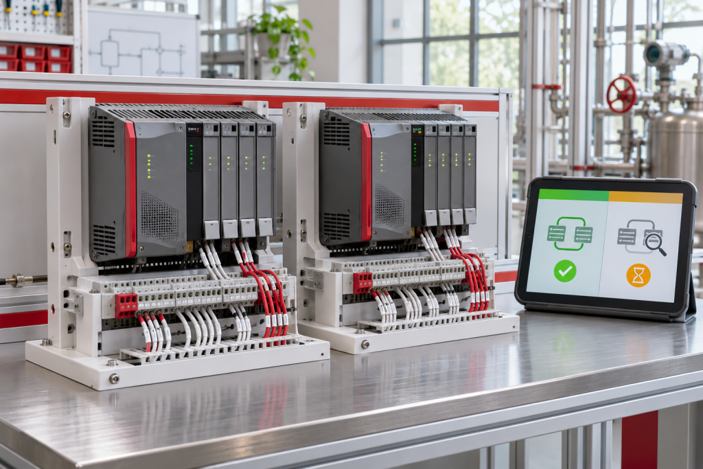
Start with the approved cabinet drawing and identify each supply, redundancy module, branch fuse, return, common and monitored alarm. Compare the drawing to the installed cabinet because field additions often change branch loading without updating the schematic. Record the control modules and field devices sharing each branch, including transmitter loops, remote I/O, network switches and solenoids. If every load on one branch drops together, focus on its upstream protection and wiring; if one device fails while neighboring loads remain stable, look locally before replacing a common supply. The ABB YPQ111A listed in the NINERMAS catalog is a relevant control-power reference, but only the complete type code and system documentation can establish suitability for a particular position.
Capture voltage at the right points
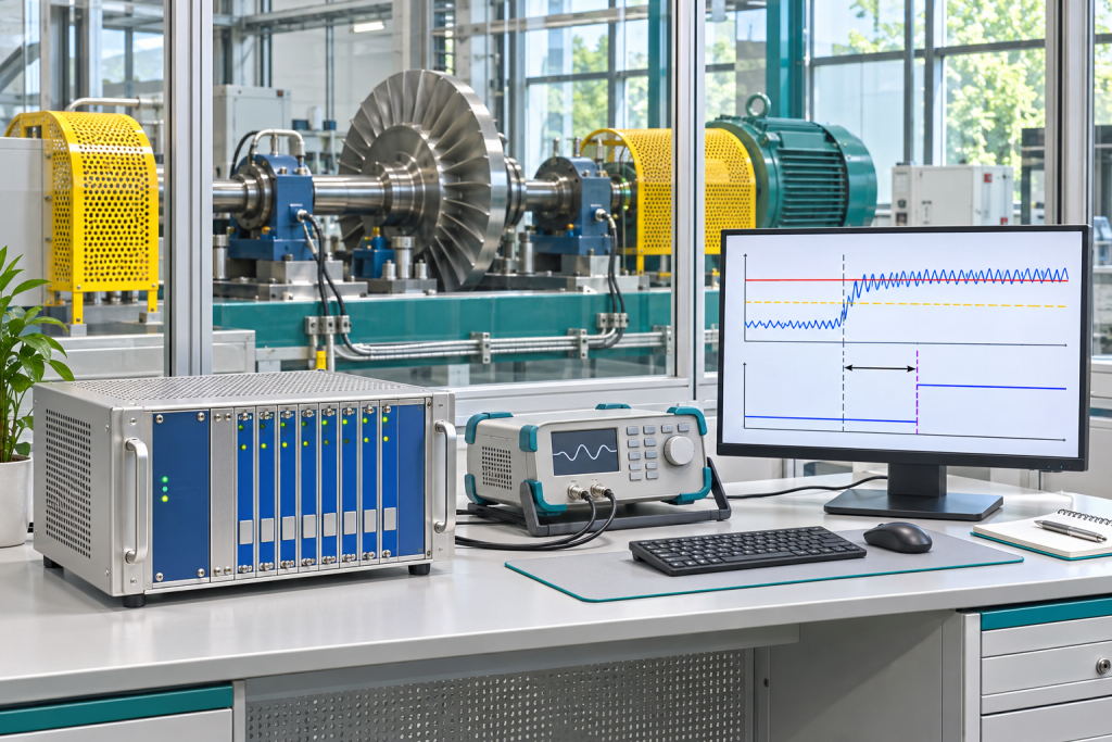
A single reading at the supply terminals can miss a transient at the far end of a loaded branch. Use a suitably rated meter or recorder under the site electrical procedure and compare voltage at the source, distribution terminals and affected load during normal operation and a representative demand change. Record minimum, duration and recovery behavior rather than writing only “24 volts present.” Check for loose terminations, corrosion, damaged ferrules, heat discoloration, undersized conductors, poor return connections and fuse holders with rising resistance. Do not probe exposed live terminals casually; use approved test points and protective equipment. A synchronized trend from the DCS event log, supply alarm contact and branch monitor helps correlate the voltage event with module resets.
The live site catalog includes ABB YPQ111A 61161007 control power module as identification references for this equipment family. Verify the full installed configuration, ratings and revision before treating any catalog match as an approved replacement.
Check load steps, wiring and protection coordination
List steady-state and peak loads, including simultaneous valve or relay operation, startup surges, newly added instruments and any downstream DC/DC converters. Compare actual branch protection with conductor ratings and the power supply manufacturer’s guidance. A fuse that is too small may nuisance-trip; oversizing protection to stop nuisance trips can remove the intended wire protection. Check whether redundancy is real at the point of failure: separate modules do not help if both share one upstream breaker, one return conductor or an overloaded downstream branch. Inspect ventilation and cabinet temperature too, since derating and thermal cycling can make a marginal supply fail only during hot shifts or peak process demand.
Use the fault record to define a spare
Before requesting a replacement, photograph the complete supply and redundancy labels, capture hardware revisions, rated input and output, alarm terminals, connector arrangement, mounting and cabinet context. Record measured load, observed dip, environmental conditions and whether the installed unit passed a controlled test. State the requested condition and acceptance evidence in the RFQ. A catalogue match is a starting point, not a blanket interchangeability claim: confirm voltage range, current capacity, redundancy behavior, diagnostics and approved system configuration with the responsible engineer. Keep the suspect unit and as-found evidence until the corrective action is confirmed; that record can distinguish an internal supply defect from an external branch fault.
Commission a change without hiding the original fault
Use an approved change plan with operations, electrical and controls staff. Define isolation, transfer or bypass boundaries, alarm handling, restoration steps and abort criteria. Verify polarity and branch labels before energizing, then test each load group and the relevant supply-failure alarm. Trend control voltage and controller status through representative operating conditions, not only at idle. Confirm no temporary jumper, test lead or inhibit remains, and update drawings, spare records and maintenance notes with the actual installed revision. If a reset was needed to recover production, document it separately from the permanent corrective action so the temporary recovery does not become the assumed fix.
Turn one voltage event into a useful baseline
Store the measured voltage at the source and affected load alongside the time, process state, cabinet temperature and branch current. Note which controller, I/O or network device logged the first restart and whether the alarm preceded or followed the voltage dip. Keep a reference trace after the repair under a representative load so future teams can compare like with like. If the source is stable but a remote load sees a drop, investigate conductor length, return path and terminal resistance; if the entire rail sags together, test upstream capacity, protection and load step. A short, repeatable record makes the next event easier to classify and helps justify a targeted spare rather than indiscriminate cabinet replacement.
Questions Maintenance Teams Ask
faq
What voltage proves a 24 VDC rail is healthy?
Should I reset the DCS before investigating the power event?
Preserve alarms, event chronology and controller diagnostics first. Follow the site recovery procedure; a reset can erase useful evidence without correcting the shared supply fault.
Can two supplies guarantee uninterrupted control power?
No. Common upstream feeds, shared returns, distribution faults and insufficient load capacity can defeat redundancy. Verify the complete failure boundary and approved transfer behavior.
What details belong in a power-module RFQ?
Send full type and revision, input/output ratings, alarm interfaces, cabinet photos, system role, measured load, required condition and acceptance-test expectations.
For a control-power inquiry, send NINERMAS the complete nameplate, cabinet and terminal photos, affected branches, load estimate, measured event and outage window. We can help identify the catalog item and compatibility evidence to review before procurement.
© 2026 NINERMAS. All rights reserved. Official Website: https://NINERMAS.com Inquiry: sale@NINERMAS.com | WhatsApp/Tel: +86 187 5021 5667
Next Step
Move the research into a cleaner RFQ.
Send the part number, quantity, condition expectation, destination, and timing details so the sourcing team can reply with better availability and lead-time context.