Original Industrial Spare Part
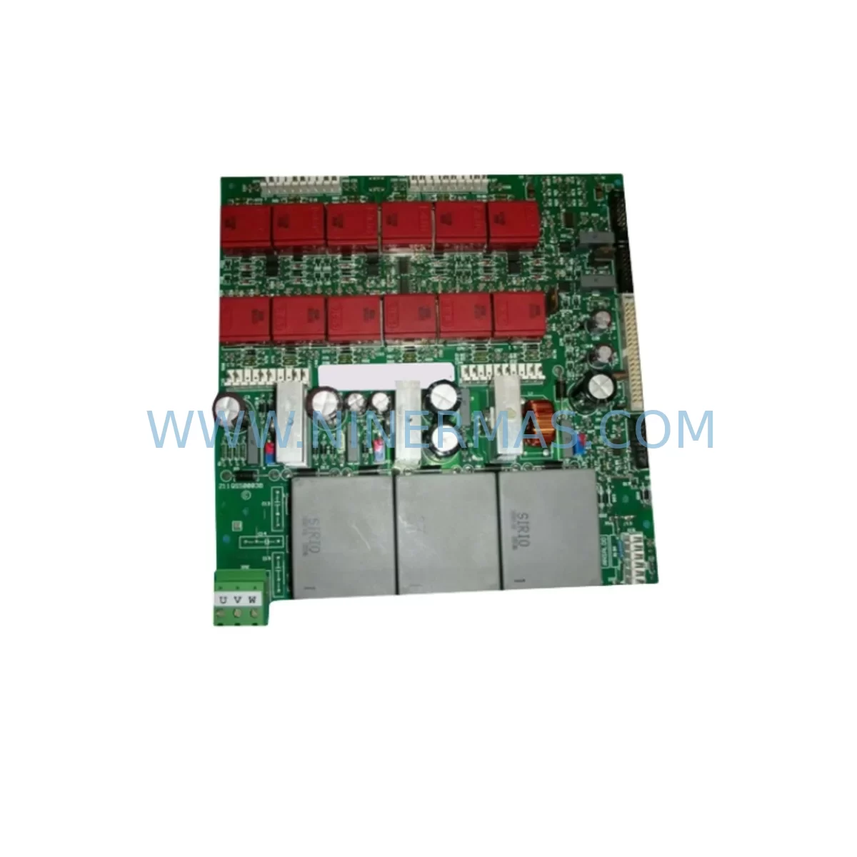
ANSALDO 211QS50003B Service-Ready Spare Part for Industrial Maintenance
Verify the part, confirm the platform family, and move straight into quotation with the right commercial details.
RFQ Ready
- SKU211QS50003B
- CategoryDCS Distributed Control Systems
- BrandANSALDO
- SupportAvailability, lead time, condition, and shipping coordination
How Buyers Usually Use This Page
- Confirm the exact part number and platform family before sending the quote request.
- Use direct email when quantity, condition, and destination are already defined internally.
- Switch to the broader brand or category archive when you need alternates nearby.
Series Navigation
Move through the most common platform families behind this part.
Product RFQ
Send this part directly for quotation.
Include quantity, required condition, destination country, and target delivery timing. Current reference: ANSALDO 211QS50003B Service-Ready Spare Part for Industrial Maintenance with SKU 211QS50003B.
ANSALDO 211QS50003B Service-Ready Spare Part for Industrial Maintenance
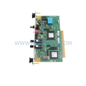
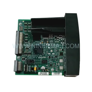
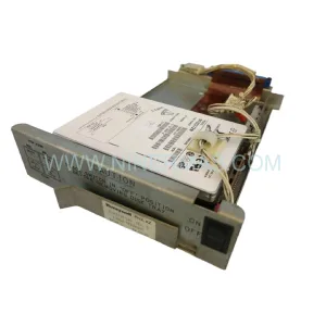
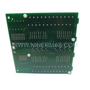
The ANSALDO 211QS50003B is an original ruggedized power trigger module engineered for continuous-duty industrial control environments where thermal stress, vibration, and electrical noise are constant operational factors. Sourced directly from verified supply channels, this spare part is tested, inspected, and shipped with a 12-month warranty to support plant maintenance teams managing legacy ANSALDO QS50-series control architectures.
For maintenance engineers responsible for uptime in process automation, power generation, or heavy industrial facilities, the 211QS50003B represents a critical line-replaceable unit (LRU). Its failure mode — typically manifesting as erratic triggering, loss of gate pulse output, or thermal shutdown — can cascade into full drive or converter outages within minutes. Holding a verified spare on the shelf is the single most effective mitigation against unplanned downtime events tied to this component.
Procurement engineers sourcing this module should confirm compatibility against the installed ANSALDO QS50 series drive or converter chassis revision. NINERMAS supplies original-specification units with full traceability documentation, pre-shipment functional verification, and export packaging rated for international freight.
Spare Maintenance Table
| Part Number | 211QS50003B |
| Brand | ANSALDO |
| Series | QS50 / 211QS Series |
| Module Type | Ruggedized Power Trigger Module |
| Function | Gate pulse generation and power triggering for thyristor/SCR drive stages |
| Application Environment | Harsh industrial: high vibration, wide temperature range, EMI-dense enclosures |
| Compatibility | ANSALDO QS50 series converters and drive control cabinets |
| Installation | Board-level replacement; observe ESD precautions and torque specifications per OEM manual |
| Condition | Original / New-equivalent, pre-shipment tested |
| Origin | Italy (ANSALDO OEM supply chain) |
| Warranty | 12 Months from date of shipment |
| Lead Time | Subject to stock confirmation — contact for availability |
| Export Packaging | Anti-static, foam-lined, rated for international air and sea freight |
Maintenance Planning for Continuous Operation
When scheduling replacement of the ANSALDO 211QS50003B power trigger module, a disciplined maintenance engineer will treat the intervention as an opportunity to audit the surrounding electrical circuit rather than a simple board swap. The trigger module operates within a tightly coupled power conversion stage, and adjacent components are subject to the same thermal and electrical stress cycles.
Begin by inspecting the ANSALDO QS50 series thyristor firing board and associated gate drive resistors for signs of heat discoloration or cracked solder joints — these are the most common co-failure components. The DC bus capacitor bank within the converter should be checked for capacitance drift and ESR increase, as degraded capacitors accelerate trigger module stress. If the drive cabinet includes an ANSALDO 211QS series synchronization card, verify its phase-lock output is clean and within specification before commissioning the replacement trigger module.
On the power supply side, confirm that the auxiliary 24 VDC control power supply feeding the trigger circuit is within tolerance — undervoltage conditions are a leading cause of premature trigger module failure and are frequently overlooked during fault isolation. Inspect the input fuse block and semiconductor fuses protecting the SCR stack; a single blown fuse can mask a deeper fault that will destroy a replacement module within hours of commissioning.
For I/O and signal integrity, review the analog reference signal wiring from the speed or current controller to the trigger module input. Shield continuity, ground loop isolation, and terminal block torque values should all be verified. Where signal isolators are installed between the controller and the drive, confirm isolator output range matches the trigger module’s input specification. Loose or corroded terminals on the DIN rail terminal blocks feeding the control circuit are a frequent source of intermittent triggering faults that are misdiagnosed as module failure.
If the installation includes a fieldbus or serial communication card for remote speed reference or diagnostics, verify communication integrity after the module replacement — a trigger module swap can disturb backplane seating and cause communication dropouts. Finally, inspect the cooling fan assembly and heat sink of the drive enclosure; restricted airflow is the primary environmental factor shortening trigger module service life in harsh-environment installations.
Site Replacement Workflow
Step 1 — Isolation and Lockout/Tagout: De-energize the drive or converter, apply LOTO per site safety procedure, and allow the DC bus to fully discharge before opening the cabinet. Verify zero-voltage with a calibrated meter across the DC bus terminals.
Step 2 — Documentation: Photograph the existing module orientation, wiring harness routing, and connector positions before removal. Record the existing module’s revision marking and compare against the replacement 211QS50003B to confirm dimensional and connector compatibility.
Step 3 — Module Removal: Disconnect gate pulse connectors and control wiring in sequence. Remove mounting fasteners using the correct torque tool. Handle the module with ESD wrist strap and place the removed unit in an anti-static bag for failure analysis or return.
Step 4 — Replacement Installation: Seat the ANSALDO 211QS50003B into the mounting position, torque fasteners to OEM specification, and reconnect all connectors in reverse removal sequence. Verify connector locking tabs are fully engaged.
Step 5 — Pre-Commissioning Checks: Before re-energizing, verify auxiliary power supply voltage, inspect all terminal connections tightened to specification, and confirm no tools or foreign objects remain in the cabinet.
Step 6 — Commissioning and Verification: Energize the drive under no-load conditions first. Verify gate pulse output waveform with an oscilloscope if available. Gradually increase load while monitoring drive current, temperature, and alarm status. Log commissioning data for the maintenance record.
This structured workflow minimizes re-work risk, protects the replacement module from installation-induced damage, and provides a documented audit trail for ISO or site maintenance management systems.
Spare Parts Support FAQ
Q1: Is the ANSALDO 211QS50003B compatible with all QS50 series drive revisions?
The 211QS50003B is designed for the ANSALDO QS50 series converter platform. However, drive revisions and regional variants may have specific sub-revision requirements. NINERMAS recommends providing your full drive nameplate data — including serial number and revision suffix — when placing an order so our technical team can confirm exact compatibility before shipment.
Q2: What pre-shipment testing is performed on this module?
Every 211QS50003B unit supplied by NINERMAS undergoes visual inspection, dimensional verification, and functional bench testing prior to packaging. Units that do not meet original ANSALDO specification are rejected. A test report is available upon request for critical plant applications.
Q3: What is the recommended spare parts holding strategy for this module?
For facilities operating multiple ANSALDO QS50 series drives, we recommend holding a minimum of one 211QS50003B per drive string as a cold standby spare. For high-criticality applications — continuous process lines, power generation auxiliaries, or single-point-of-failure drives — a hot standby spare at the cabinet level is advisable. Long lead times for legacy ANSALDO components make proactive stocking essential for downtime risk management.
Q4: What does the 12-month warranty cover?
NINERMAS provides a 12-month warranty from the date of shipment covering manufacturing defects and functional failure under normal operating conditions. The warranty does not cover damage resulting from incorrect installation, overvoltage events, or operation outside the module’s rated environmental parameters. Warranty claims are supported with replacement or credit at NINERMAS’s discretion following failure analysis.
—
| Product Series | Other series |
|---|
Catalog Continuation
Alternative parts within DCS Distributed Control Systems.
Stay inside the same system family when you need substitutes, adjacent modules, or a broader shortlist for procurement review.