Original Industrial Spare Part
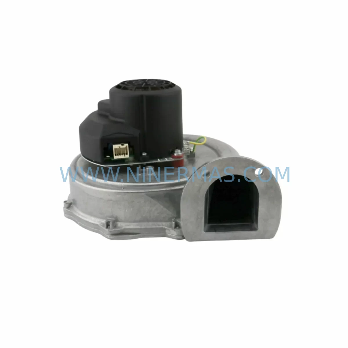
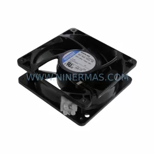
ebm-papst RG175/2000-3633-010204 Retrofit Fan for Legacy Systems
Verify the part, confirm the platform family, and move straight into quotation with the right commercial details.
RFQ Ready
- SKURG175/2000-3633-010204 AR30-07-PFA2 0150-76682
- CategoryPLC & Industrial Automation Modules
- Brandebm-papst
- SupportAvailability, lead time, condition, and shipping coordination
How Buyers Usually Use This Page
- Confirm the exact part number and platform family before sending the quote request.
- Use direct email when quantity, condition, and destination are already defined internally.
- Switch to the broader brand or category archive when you need alternates nearby.
Series Navigation
Move through the most common platform families behind this part.
Product RFQ
Send this part directly for quotation.
Include quantity, required condition, destination country, and target delivery timing. Current reference: ebm-papst RG175/2000-3633-010204 Retrofit Fan for Legacy Systems with SKU RG175/2000-3633-010204 AR30-07-PFA2 0150-76682.
ebm-papst RG175/2000-3633-010204 Retrofit Fan for Legacy Systems: Seamless Compatibility for Aging Automation Infrastructure
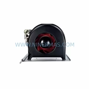
The ebm-papst RG175/2000-3633-010204 is a ruggedized centrifugal blower fan module engineered for demanding industrial environments. As original equipment manufacturers discontinue legacy cooling components, maintenance engineers and system integrators face increasing pressure to source verified retrofit-compatible replacements that preserve control cabinet thermal management without triggering full system redesigns. This unit — carrying the secondary reference AR30-07-PFA2 and cross-reference 0150-76682 — is stocked and pre-shipment tested to serve as a direct or near-direct replacement in legacy automation enclosures, control panels, and drive cooling assemblies where the original RG175 series was specified.
With a 12-month warranty covering manufacturing defects and pre-shipment functional verification, this blower module is suitable for critical retrofit projects where downtime must be minimized and replacement confidence is non-negotiable.
Upgrade Compatibility Table
| Parameter | Details |
|---|---|
| SKU / Part Number | RG175/2000-3633-010204 | AR30-07-PFA2 | 0150-76682 |
| Brand / Manufacturer | ebm-papst (Germany) |
| Series | RG175 |
| Product Type | Centrifugal Blower Fan Module |
| Mounting Interface | Standard RG175 frame footprint; confirm backplate clearance before installation |
| Communication / Control | PWM speed control signal compatible; verify signal voltage level with host controller |
| Replacement Compatibility | Direct replacement for discontinued RG175/2000 variants; cross-reference 0150-76682 confirmed |
| Installation Requirement | Confirm terminal wiring polarity, connector type, and airflow direction before commissioning |
| Commissioning Note | Verify tachometer feedback signal compatibility with existing drive or PLC I/O module |
| Warranty | 12 months from shipment date; covers manufacturing defects under normal operating conditions |
| Pre-Shipment Testing | Functional run test performed; rotation, speed feedback, and current draw verified |
| Origin | Germany (DE) |
Retrofit Planning for Existing Automation Systems
Replacing a blower fan module in a live automation environment requires careful coordination across multiple system layers. The RG175/2000-3633-010204 is commonly found in control cabinets housing frequency inverters, servo drives, and PLC rack assemblies where thermal management is critical to sustained uptime. Before committing to a swap, engineers should audit the existing installation for the following:
Power Supply Capacity: Confirm that the 24 VDC or 48 VDC rail feeding the fan module has sufficient headroom for the replacement unit’s inrush and steady-state current draw. In cabinets where an ebm-papst power supply module or a third-party DIN-rail PSU is shared across multiple loads — including I/O modules, signal isolators, and communication gateways — a current budget review is essential before installation.
Terminal Wiring and Connector Compatibility: The RG175 series uses a specific connector housing. When migrating from an older RG175/2000 variant, verify that the existing wiring harness connector matches the replacement unit’s pin-out. In some legacy installations, field-wired terminal blocks were used instead of factory connectors; in these cases, a short adapter harness may be required. This is particularly relevant in cabinets that also house R2E175-AC77-15 axial fan units or R2E225-BD92-09 modules on adjacent mounting positions, where wiring looms are often shared.
Backplane and Rack Interface: In modular control rack environments — such as those using Siemens S7-300 or S7-400 backplanes, B&R X20 system racks, or Beckhoff CX series mounting rails — the fan module’s physical footprint must be confirmed against available installation space. The RG175 frame is a standard centrifugal form factor, but adjacent modules such as K2E225-AA01-09 cross-flow fan assemblies or fan tray bracket kits may occupy shared mounting positions.
PWM Signal and Tachometer Feedback: Many legacy drive systems use a 0–10 V or PWM speed reference signal to regulate fan speed dynamically. Confirm that the host controller’s analog output module or digital I/O card is compatible with the replacement fan’s control input. In systems where a dedicated fan speed controller or RS485 communication module manages multiple cooling zones, the new unit’s speed feedback (tachometer pulse) signal must be validated against the controller’s expected pulse-per-revolution count.
Airflow Direction and Thermal Zoning: The RG175/2000-3633-010204 is a centrifugal blower with a defined inlet and outlet orientation. Reversing airflow direction in a sealed control cabinet can cause hot-spot migration toward sensitive components such as IGBT modules, capacitor banks, or HMI panel backlights. Confirm the airflow path against the original cabinet thermal design before final installation.
HMI and SCADA Integration: In systems where fan status is monitored via a Siemens TP700 or TP1200 HMI panel, or through a SCADA OPC-UA data point, verify that the tachometer feedback signal is correctly mapped to the existing screen object or alarm tag. Failure to update the HMI screen or PLC program tag after a fan replacement can result in false fault alarms or missed maintenance alerts.
Signal Isolation: In electrically noisy environments — common in cabinets housing variable frequency drives, servo amplifiers, or high-current contactors — a signal isolator or galvanic isolation relay may be required between the fan’s tachometer output and the PLC digital input card. This is standard practice when integrating replacement fan modules into legacy Omron CJ2M or Mitsubishi Q-series PLC systems.
Downtime Control During System Migration
Minimizing production downtime during a fan module replacement is a primary concern for maintenance teams operating continuous-process or high-availability manufacturing lines. The following approach is recommended for the RG175/2000-3633-010204 retrofit:
Pre-Staging and Bench Verification: Before the scheduled maintenance window, bench-test the replacement unit against a 24 VDC bench supply and verify rotation direction, speed feedback pulse output, and current draw. This eliminates the risk of discovering a wiring or compatibility issue during the live replacement window.
Program Logic Preservation: If the host PLC — whether a Siemens S7-1500, Beckhoff CX5140, or B&R X20CP1586 — monitors fan status as part of a thermal protection interlock, temporarily bypass or mask the fan fault input in the PLC program before removing the old unit. Document the bypass clearly and restore the interlock immediately after the new unit is confirmed operational. Never leave a thermal protection interlock permanently disabled.
Parallel Cooling Continuity: In cabinets with redundant cooling paths — for example, where both an RG175 blower and an R2E225-BD92-09 axial fan operate simultaneously — the axial fan can maintain partial cooling during the blower swap, reducing thermal risk to drive components during the replacement window.
Post-Installation Commissioning: After installation, run the system at reduced load for a minimum of 15 minutes while monitoring cabinet internal temperature via the existing thermal sensor or a handheld IR thermometer. Confirm that the tachometer feedback signal is stable and that no fan fault alarms are active on the HMI or SCADA system before returning the line to full production.
Documentation and Traceability: Record the replacement unit’s serial number, installation date, and pre-shipment test report reference in the cabinet maintenance log. This supports 12-month warranty claims and provides traceability for future audits or insurance inspections.
Retrofit Support FAQ
Q1: Is the RG175/2000-3633-010204 a direct drop-in replacement for the original RG175/2000 series?
In most installations, yes. The RG175/2000-3633-010204 shares the standard RG175 frame footprint and electrical interface. However, always verify connector pin-out, airflow direction, and PWM signal voltage compatibility against your specific cabinet wiring documentation before installation. Cross-reference 0150-76682 and AR30-07-PFA2 can be used to confirm equivalence with your original procurement records.
Q2: What pre-shipment testing is performed before dispatch?
Each unit undergoes a functional run test covering rotation verification, speed feedback (tachometer) signal output, and steady-state current draw measurement. Test results are retained for warranty reference. Units that fail any parameter are quarantined and not shipped. The 12-month warranty covers manufacturing defects identified under normal operating conditions from the shipment date.
Q3: How do I confirm wiring compatibility with my existing control cabinet?
Refer to the original ebm-papst RG175 series datasheet for connector pin-out and signal specifications. Compare against your cabinet wiring diagram. If the original connector housing is no longer available, a standard JST or Molex adapter harness can be fabricated using the pin-out data. For cabinets with shared wiring looms serving multiple fan positions, isolate the target fan circuit before disconnecting.
Q4: What is the lead time and stock availability?
This unit is held in ready-to-ship inventory. Standard dispatch is within 1–3 business days of order confirmation. For bulk orders or reserved inventory agreements supporting long-term maintenance contracts, contact our sales team to discuss dedicated stock allocation. All units are covered by a 12-month warranty from the shipment date.
| Product Series | Legacy |
|---|
Catalog Continuation
More ebm-papst modules in the catalog.
Use the brand lane to compare nearby part numbers, platform-adjacent modules, and other inquiry-ready listings before sending your final RFQ.
Catalog Continuation
Alternative parts within PLC & Industrial Automation Modules.
Stay inside the same system family when you need substitutes, adjacent modules, or a broader shortlist for procurement review.
SKU: PFXPP170CA66K00N00
Pro-face PFXPP170CA66K00N00 Service-Ready Spare Part

SKU: 6SL3224-0BE32-2UA0
Siemens 6SL3224-0BE32-2UA0 Retrofit PM240 Power Module