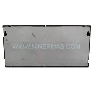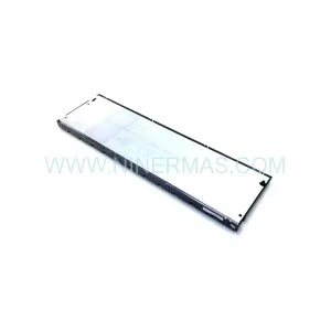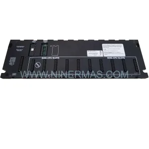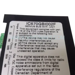
Original Industrial Spare Part
AMAT 0100-76124 Retrofit Servo Drive for Legacy Systems
Verify the part, confirm the platform family, and move straight into quotation with the right commercial details.
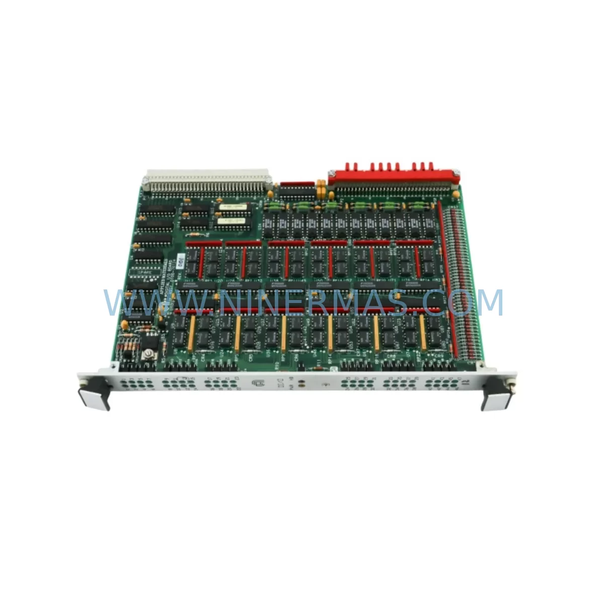
RFQ Ready
- SKU0100-76124 XENUS PLUS 800-1763 MY1B50G-860
- CategoryPLC & Industrial Automation Modules
- BrandApplied Materials
- SupportAvailability, lead time, condition, and shipping coordination
How Buyers Usually Use This Page
- Confirm the exact part number and platform family before sending the quote request.
- Use direct email when quantity, condition, and destination are already defined internally.
- Switch to the broader brand or category archive when you need alternates nearby.
Series Navigation
Move through the most common platform families behind this part.
Product RFQ
Send this part directly for quotation.
Include quantity, required condition, destination country, and target delivery timing. Current reference: AMAT 0100-76124 Retrofit Servo Drive for Legacy Systems with SKU 0100-76124 XENUS PLUS 800-1763 MY1B50G-860.
AMAT 0100-76124 Retrofit Servo Drive for Legacy Systems: Seamless Compatibility and Smooth Upgrade
The Applied Materials AMAT 0100-76124 is a retrofit-compatible servo drive assembly engineered for legacy semiconductor fabrication equipment and precision motion control platforms. As original equipment manufacturers discontinue support for aging automation architectures, maintenance engineers and system integrators face increasing pressure to source verified replacement components that maintain process continuity without requiring full-system redesigns. The AMAT 0100-76124 addresses this challenge directly — offering a pre-tested, drop-in compatible solution for facilities operating legacy AMAT process tools, Xenus Plus-based motion subsystems, and related automation infrastructure.
This unit is particularly relevant in environments where the Copley Controls Xenus Plus XPL-230-36 servo drive has reached end-of-life or where the associated 800-1763 motion interface card is no longer available through standard distribution channels. The 0100-76124 assembly integrates into existing backplane configurations without requiring firmware re-architecture, making it a preferred choice for facilities prioritizing minimal downtime and validated interoperability.
Upgrade Compatibility Table
| Parameter | Legacy Configuration | AMAT 0100-76124 Retrofit |
|---|---|---|
| Interface Type | Proprietary AMAT backplane connector | Direct-compatible backplane interface |
| Communication Protocol | DeviceNet / RS-232 serial | DeviceNet / RS-232 compatible |
| Power Supply Requirement | 24 VDC control, ±15 VDC analog | 24 VDC control, ±15 VDC analog |
| Mounting / Form Factor | Standard AMAT card cage slot | Same card cage slot — no mechanical modification |
| Terminal Wiring | OEM harness connector | Compatible with existing OEM harness |
| Program Compatibility | Legacy AMAT motion recipe files | Verified compatible — no recipe rewrite required |
| HMI Screen Mapping | Existing AMAT operator interface | No HMI screen remapping required |
| Replacement Recommendation | Direct swap for 0100-76124 OEM unit | Confirmed drop-in replacement |
| Pre-Shipment Testing | N/A (OEM discontinued) | Full functional test performed before dispatch |
| Warranty | OEM warranty expired | 12-Month Warranty included |
Retrofit Planning for Existing Automation Systems
Successful integration of the AMAT 0100-76124 into a legacy production environment requires systematic pre-installation verification across several interdependent subsystems. Engineers should begin by auditing the existing card cage and backplane for physical slot availability and confirming that the 24 VDC control power rail and ±15 VDC analog supply remain within specification. Power capacity is a critical first checkpoint — an undersized or degraded power supply module can cause intermittent faults that are difficult to diagnose after installation.
Terminal wiring should be documented before removal of the legacy unit. The OEM harness connector used with the original 0100-76124 is typically retained without modification, but pin continuity should be verified with a multimeter before reconnection. In systems where the Copley Controls Xenus Plus XPL-230-36 was installed as a motion amplifier alongside the AMAT assembly, engineers should confirm that the amplifier’s enable signal and fault relay wiring remain intact and correctly routed to the new unit’s I/O interface.
Backplane address configuration is the next critical step. In multi-axis AMAT motion platforms, each servo drive card occupies a defined slot address that maps directly to the motion controller’s axis table. Incorrect address assignment — even by a single slot — will cause the system controller to fail axis initialization. This is especially relevant in systems using Allen-Bradley 1756-L72S ControlLogix processors or similar rack-based controllers where axis-to-slot mapping is defined in the motion configuration file.
Communication link verification follows address assignment. In facilities where DeviceNet is the primary fieldbus, the network segment should be scanned after installation to confirm the new node appears at the expected MAC ID. In systems that have been partially migrated to EtherCAT, an EtherCAT gateway or bridge module may be present in the control cabinet — its configuration should be reviewed to ensure the servo drive node is correctly enumerated. Signal isolators installed between the drive and the process I/O rack should also be inspected for correct channel mapping and isolation voltage ratings.
Program compatibility is a frequent concern during legacy retrofits. The AMAT 0100-76124 is designed to accept the same motion recipe parameters as the original OEM unit, meaning that existing AMAT process programs — including wafer handling sequences, chuck positioning routines, and end-effector motion profiles — do not require rewriting. However, engineers should perform a dry-run simulation with the process chamber isolated before returning the tool to production. HMI screens on the AMAT operator interface panel should be reviewed to confirm that axis status indicators, fault codes, and jog controls respond correctly to the new unit.
For facilities managing I/O expansion alongside the servo drive replacement, the installation window is an opportunity to audit adjacent modules. SMC MY1B50G-860 pneumatic actuators connected to the motion platform should be inspected for seal condition and stroke calibration. Programming cables used for drive parameter backup — such as the Copley Controls CME 2 USB interface cable — should be on hand during commissioning to allow parameter verification and, if necessary, parameter restore from a previously saved configuration file.
Downtime Control During System Migration
Minimizing unplanned downtime is the primary operational concern when replacing a servo drive in a live semiconductor fabrication environment. The AMAT 0100-76124 is pre-tested at our facility before dispatch, which eliminates the most common source of extended downtime: receiving a replacement unit that requires additional bench testing or parameter configuration before it can be installed.
To further compress the installation window, engineers should prepare a pre-swap checklist that includes: saving the current axis parameter set from the existing drive (if still functional), photographing all wiring connections before disconnection, labeling each harness connector with its destination terminal, and confirming that a spare 24 VDC fuse and backplane retaining hardware are available on-site. These steps typically reduce the physical swap time to under two hours for a single-axis replacement.
Protecting the original program logic is equally important. Before beginning any hardware work, the full motion program should be backed up to a secure network location or USB drive. In systems controlled by an Allen-Bradley 1756-L72S or similar ControlLogix processor, the project file should be exported from Studio 5000 and stored offline. This ensures that even in the unlikely event of a controller fault during the swap, the program can be restored without delay.
Field commissioning after installation should follow a structured sequence: power-on with the process chamber isolated, axis enable with no load, low-speed jog test across the full travel range, and finally a full-speed motion profile test with the process load engaged. Each step should be documented with a timestamp and the name of the commissioning engineer. This documentation supports warranty claims and provides a traceable record for quality audits.
Retrofit Support FAQ
Q1: Is the AMAT 0100-76124 a direct replacement for the original OEM unit, or does it require parameter reconfiguration?
The 0100-76124 is supplied as a direct drop-in replacement. It is pre-configured and tested to match the original OEM parameter set. In most installations, no parameter reconfiguration is required. However, we recommend verifying axis address assignment and performing a low-speed jog test before returning the tool to production.
Q2: What pre-shipment testing is performed, and how is the test result documented?
Every unit undergoes full functional testing at our facility prior to dispatch. Testing covers power-on self-test, communication link verification, enable/disable signal response, and motion profile execution. A test report is included with each shipment and is available on request for quality audit purposes.
Q3: What is the warranty coverage, and what does it include?
All AMAT 0100-76124 units are covered by a 12-month warranty from the date of shipment. The warranty covers manufacturing defects and functional failures under normal operating conditions. It does not cover damage resulting from incorrect installation, overvoltage events, or physical impact. Warranty claims are processed within 5 business days of receipt of the returned unit.
Q4: What is the typical lead time, and do you maintain stock for urgent requirements?
We maintain reserved inventory of the AMAT 0100-76124 to support urgent maintenance requirements. Standard lead time for in-stock units is 3–5 business days for international shipments. For critical production environments, expedited dispatch is available — please contact our sales team directly to confirm current stock levels and arrange priority shipping.
| Product Series | Legacy |
|---|---|
| Country of Origin | US |
Catalog Continuation
More Applied Materials modules in the catalog.
Use the brand lane to compare nearby part numbers, platform-adjacent modules, and other inquiry-ready listings before sending your final RFQ.
SKU: 0200-06355 1220-01011 0242-02385
AMAT 0200-06355 Retrofit Ceramic Blade for Legacy Systems
SKU: A 10 TTT MKS AS00800-10-1 0190-47445 SG25SA-P01U3 SGMP-01U314M
AMAT 0190-47445 Retrofit PCB Controller for Legacy Systems
SKU: 0270-03850 0040-48318 TT2301R2-1-NES-LAM 27-326390-00
AMAT 0270-03850 Retrofit Cover Top Assy for Legacy Systems
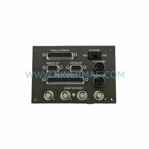
SKU: 0100-70034 CDN396R, AS01396-6-15 0190-43360 0190-29030 SST-EDN-1
AMAT 0100-70034 Retrofit VGA Interconnect for Legacy Systems
Catalog Continuation
Alternative parts within PLC & Industrial Automation Modules.
Stay inside the same system family when you need substitutes, adjacent modules, or a broader shortlist for procurement review.
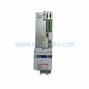
SKU: HDD02.2-W040N-HS12-01-FW FWA-DIAX04-ELS-05VRS-MS
Rexroth HDD02.2-W040N-HS12-01-FW Service-Ready Spare Part
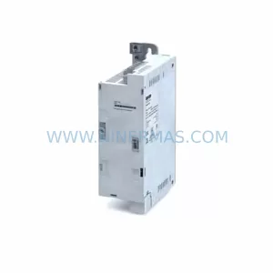
SKU: I5DAE375F10010000S
Lenze I5DAE375F10010000S Service-Ready Spare Part for Industrial Maintenance