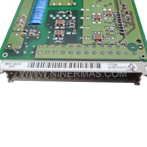
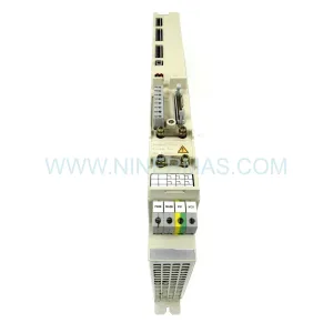
Original Industrial Spare Part
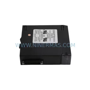
LAM X10-14210100 Retrofit-Compatible Power Supply for Legacy Systems
Verify the part, confirm the platform family, and move straight into quotation with the right commercial details.
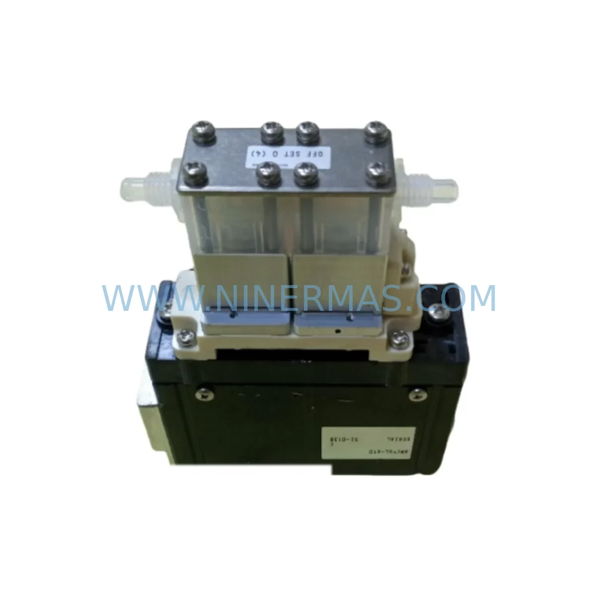
RFQ Ready
- SKUX10-14210100
- CategoryPLC & Industrial Automation Modules
- BrandLAM
- SupportAvailability, lead time, condition, and shipping coordination
How Buyers Usually Use This Page
- Confirm the exact part number and platform family before sending the quote request.
- Use direct email when quantity, condition, and destination are already defined internally.
- Switch to the broader brand or category archive when you need alternates nearby.
Series Navigation
Move through the most common platform families behind this part.
Product RFQ
Send this part directly for quotation.
Include quantity, required condition, destination country, and target delivery timing. Current reference: LAM X10-14210100 Retrofit-Compatible Power Supply for Legacy Systems with SKU X10-14210100.
LAM X10-14210100 Retrofit-Compatible Power Supply for Legacy Systems
The LAM X10-14210100 is a ruggedized, retrofit-compatible power supply module engineered to support the lifecycle extension of aging industrial control systems operating in harsh process environments. Designed as a direct functional replacement for discontinued power supply assemblies within the LAM X10 platform, this module enables maintenance engineers and automation teams to restore or upgrade control cabinet power infrastructure without requiring a full system overhaul. Whether you are managing a brownfield retrofit, replacing an end-of-life power rail, or stabilizing a legacy control enclosure ahead of a phased migration, the X10-14210100 delivers the electrical performance and mechanical compatibility required for seamless integration.
Industrial facilities running legacy LAM X10-series control architectures frequently encounter obsolescence challenges when original power supply modules reach end-of-life. Sourcing a verified retrofit-compatible replacement such as the X10-14210100 eliminates the need to redesign the entire power distribution scheme within the control cabinet. The module maintains the original terminal block pinout and DIN rail mounting footprint, allowing technicians to complete a like-for-like swap with minimal disruption to adjacent I/O modules, communication cards, and backplane assemblies already installed in the rack.
Upgrade Compatibility Table
| Parameter | Details |
|---|---|
| SKU / Part Number | LAM X10-14210100 |
| Series | LAM X10 |
| Module Function | Ruggedized Power Supply Module |
| Mounting | DIN Rail / Panel Mount (confirm existing rail type before installation) |
| Terminal Interface | Screw-terminal block; verify torque spec and wire gauge against original wiring diagram |
| Backplane Compatibility | LAM X10-series backplane; confirm slot addressing and bus voltage before insertion |
| Communication Compatibility | Compatible with existing X10 rack communication bus; no protocol migration required for in-series replacement |
| Replacement Recommendation | Direct retrofit replacement for discontinued LAM X10 power supply variants; confirm output voltage and current rating against load requirements |
| Commissioning Notes | Verify input voltage range, output load capacity, and inrush current tolerance before energizing; perform functional test under partial load prior to full production restart |
| Warranty | 12-Month Warranty — covers manufacturing defects and functional failure under normal operating conditions |
Retrofit Planning for Existing Automation Systems
Successful integration of the LAM X10-14210100 into an existing control architecture requires a structured pre-installation assessment. Before removing the failed or obsolete power supply, engineers should document the current wiring layout, terminal assignments, and load distribution across all powered modules in the rack. In a typical X10-series control cabinet, the power supply feeds a combination of digital I/O modules, analog input cards, and communication interface modules simultaneously. Any interruption to the power rail during replacement will affect all downstream devices, including any connected HMI panels displaying live process data.
When planning the retrofit, confirm the output voltage and current capacity of the X10-14210100 against the aggregate load of all installed modules. If the control cabinet also houses a dedicated CPU or controller module drawing from the same power bus, calculate the combined current draw including worst-case I/O scan cycle loads. In systems where a separate 24 VDC power supply feeds field-side sensors and actuators through isolated terminal strips, the X10-14210100 replacement scope is limited to the controller-side bus — field wiring remains undisturbed.
For facilities running mixed-generation racks that include both legacy X10 modules and newer communication gateway cards, verify that the replacement power supply’s output ripple and noise specifications remain within tolerance for sensitive analog input modules. Signal isolators installed between field transmitters and analog input cards can help buffer any transient noise introduced during the power supply changeover. Similarly, if the rack includes a Modbus RTU or PROFIBUS DP communication module connecting the PLC to upstream SCADA or DCS systems, confirm that the communication link remains stable during the hot-swap window or plan for a controlled communication timeout and reconnect sequence.
Backplane slot addressing should be verified before reinserting the replacement module. In some X10-series configurations, the power supply occupies a dedicated slot with a fixed address that the CPU module references during startup diagnostics. If the replacement module is inserted into an incorrect slot position, the controller may generate a hardware fault on the next power cycle. Review the rack layout diagram and confirm the physical slot number matches the configuration stored in the controller’s hardware definition file. If the original programming software — such as a legacy ladder logic editor or function block diagram tool — is still available on the engineering workstation, perform a hardware configuration comparison before restarting the system.
In cases where the control cabinet also contains a programming cable interface or a dedicated communication port for firmware updates, ensure that the replacement power supply does not obstruct physical access to these ports. Some X10-series enclosures are space-constrained, and the power supply module’s connector orientation may affect cable routing for adjacent programming interfaces. Measure the available installation depth and confirm that the X10-14210100’s physical dimensions are compatible with the existing enclosure before committing to the replacement.
Downtime Control During System Migration
Minimizing unplanned downtime during a power supply replacement on a live production line requires careful sequencing and preparation. Begin by placing the process under manual control or transferring supervisory authority to a redundant control loop if available. If the system operates under a distributed control architecture where multiple controllers share process responsibility, isolate the affected controller from the network before de-energizing the rack to prevent cascading fault alarms across the plant-wide SCADA system.
Before removing the original power supply, capture a full backup of the controller program, including all data tables, PID tuning parameters, and communication configuration files. Store the backup on an external device independent of the controller’s internal memory. This ensures that if the replacement module triggers an unexpected cold-start sequence, the original program logic can be restored without relying on the controller’s battery-backed RAM, which may have degraded over years of continuous operation in a harsh environment.
Once the X10-14210100 is installed and the rack is re-energized, perform a staged power-up sequence: first verify that the power supply’s status indicators confirm correct output voltage before allowing the CPU module to complete its initialization routine. Monitor the I/O module status LEDs across the rack to confirm that all cards return to their pre-shutdown states. If any I/O module fails to initialize correctly, check the backplane seating and terminal connections before assuming a module fault. In many legacy system retrofits, loose terminal screws or oxidized connector contacts — rather than module failures — are the root cause of post-replacement commissioning issues.
For systems connected to HMI panels, verify that all display screens return to their normal operating views and that no persistent alarm conditions remain latched from the shutdown event. Clear any latched alarms only after confirming that the underlying process conditions are within normal operating range. Document the replacement event, including the date, technician name, module serial number, and any deviations from the standard commissioning checklist, to support future maintenance audits and warranty claims.
Retrofit Support FAQ
Q1: Is the LAM X10-14210100 a direct drop-in replacement for the original X10 power supply?
The X10-14210100 is designed as a retrofit-compatible replacement for discontinued LAM X10-series power supply modules. In most configurations, it maintains the same terminal block layout and mounting footprint as the original. However, always verify the output voltage rating, current capacity, and connector pinout against your specific installation’s wiring diagram before completing the swap. Minor hardware revisions across X10 production runs may require terminal adapter plates or wiring adjustments.
Q2: What pre-shipment testing is performed on the X10-14210100?
Each LAM X10-14210100 unit undergoes functional output testing prior to shipment, including verification of output voltage regulation, load response, and protection circuit activation under simulated fault conditions. Units are inspected for physical integrity and connector condition before packaging. A 12-month warranty covers manufacturing defects and functional failures under normal operating conditions from the date of delivery.
Q3: Can the X10-14210100 operate in high-temperature or high-vibration environments?
The X10-14210100 is rated for ruggedized industrial environments. Confirm the module’s operating temperature range and vibration tolerance specifications against your installation’s environmental profile — particularly in applications involving heavy machinery, compressor rooms, or outdoor enclosures subject to thermal cycling. If the original module included conformal coating for humidity resistance, verify whether the replacement carries equivalent protection.
Q4: What is the lead time and stock availability?
NINERMAS maintains inventory of the LAM X10-14210100 to support urgent maintenance and planned retrofit projects. Contact our team at sale@ninermas.com or +0086 187 5021 5667 to confirm current stock levels, lead time, and volume pricing for spare parts programs. We support both single-unit emergency orders and long-term blanket purchase arrangements for facilities managing ongoing legacy system maintenance schedules.
| Product Series | Legacy |
|---|
Catalog Continuation
More LAM modules in the catalog.
Use the brand lane to compare nearby part numbers, platform-adjacent modules, and other inquiry-ready listings before sending your final RFQ.
SKU: VME-LTNI-S4 B105-0102
LAM VME-LTNI-S4 B105-0102 Retrofit Network Interface Module
Catalog Continuation
Alternative parts within PLC & Industrial Automation Modules.
Stay inside the same system family when you need substitutes, adjacent modules, or a broader shortlist for procurement review.
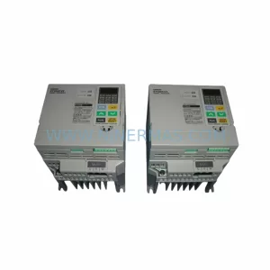
SKU: 3G3EV-AB007M-E
OMRON 3G3EV-AB007M-E Retrofit-Compatible VFD for Legacy Systems
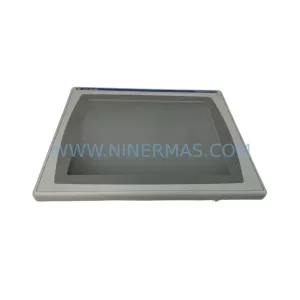
SKU: 2711P-RDT15C SER B
Allen-Bradley 2711P-RDT15C SER B Industrial Spare Part