Original Industrial Spare Part
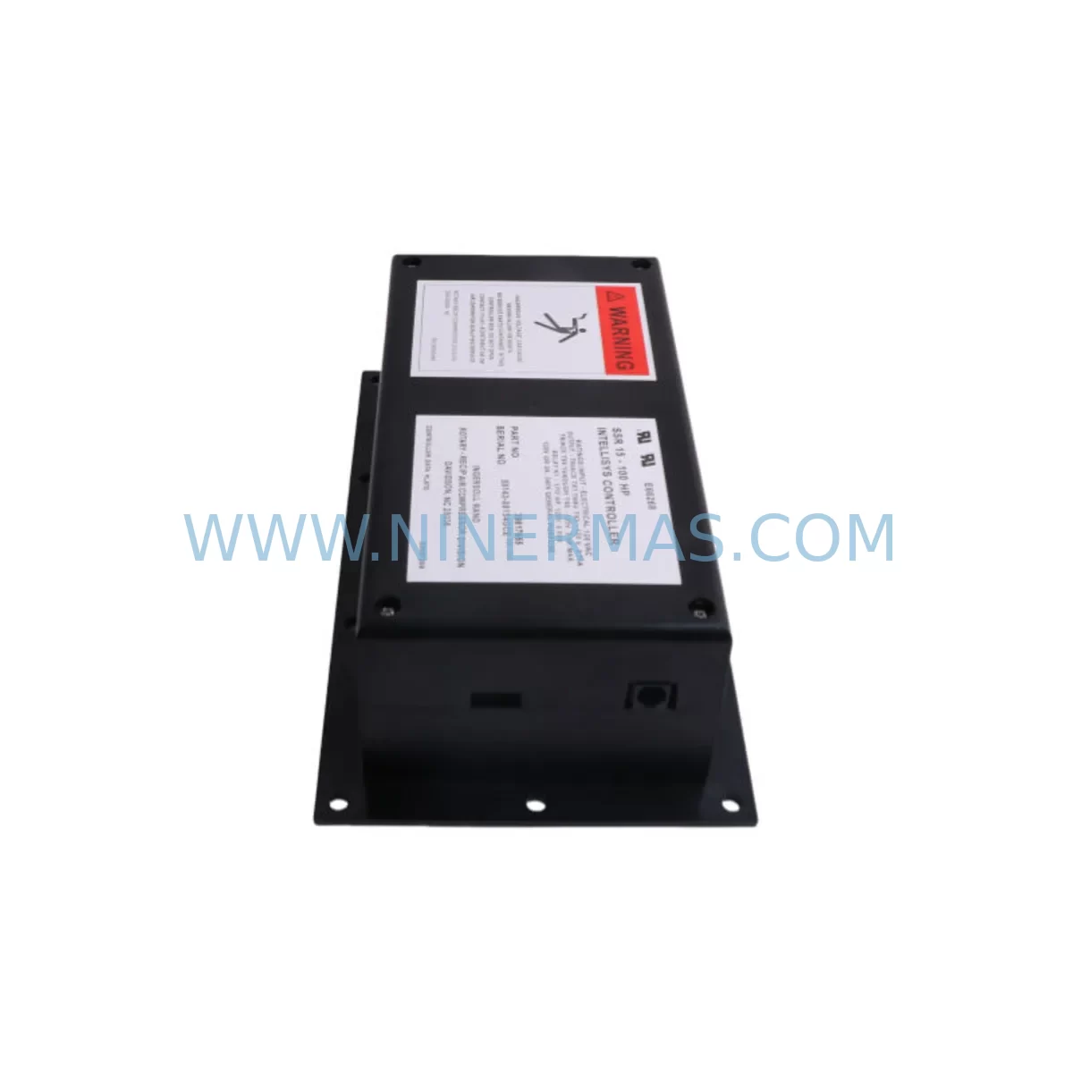
Ingersoll Rand 39817655 Retrofit Controller for Legacy Systems
Verify the part, confirm the platform family, and move straight into quotation with the right commercial details.
RFQ Ready
- SKU39817655
- CategoryPLC & Industrial Automation Modules
- BrandIngersoll Rand
- SupportAvailability, lead time, condition, and shipping coordination
How Buyers Usually Use This Page
- Confirm the exact part number and platform family before sending the quote request.
- Use direct email when quantity, condition, and destination are already defined internally.
- Switch to the broader brand or category archive when you need alternates nearby.
Series Navigation
Move through the most common platform families behind this part.
Product RFQ
Send this part directly for quotation.
Include quantity, required condition, destination country, and target delivery timing. Current reference: Ingersoll Rand 39817655 Retrofit Controller for Legacy Systems with SKU 39817655.
Ingersoll Rand 39817655 Retrofit Controller for Legacy Systems
The Ingersoll Rand 39817655 is a core Intellisys controller module designed for seamless integration into legacy rotary screw compressor systems. As industrial facilities face increasing pressure to maintain aging air compression infrastructure without full system replacement, the 39817655 provides a proven retrofit path that preserves existing wiring harnesses, terminal layouts, and control logic while delivering modern reliability. This unit is a direct replacement for discontinued Intellisys controller variants found across the SSR, UP6, and R-Series compressor platforms, making it an essential spare for maintenance teams managing end-of-life equipment.
When planning a retrofit or spare parts replacement using the 39817655, engineers must carefully evaluate several critical compatibility factors before installation. Power supply capacity is the first checkpoint: the existing 24VDC control circuit must be verified against the module’s rated input range, and the 39853247 power supply module should be inspected for output stability before the new controller is energized. Terminal wiring must be mapped against the original schematic, as pin assignments on the 39817655 differ slightly from earlier Intellisys generations — particularly on the analog input terminals used for pressure and temperature signal conditioning.
Backplane interface compatibility is equally important. The 39817655 mounts to the standard Intellisys backplane used across the SSR-EP and SSR-UP series, but technicians should confirm that the backplane connector on the 39894597 I/O expansion board is free of corrosion and that the ribbon cable seating is secure. Module addressing must also be reconfigured after installation: the Intellisys system uses a DIP-switch-based node address scheme, and the replacement controller must be set to match the original address to avoid communication conflicts with the 39807532 communication interface module.
Program compatibility is a frequent concern during Intellisys controller replacement. The 39817655 retains the standard Intellisys firmware architecture, which means existing compressor setpoints — including load/unload pressure bands, star-delta timing, and service interval counters — can typically be re-entered manually using the 39877618 operator display panel. If the original controller was still functional at the time of removal, it is strongly recommended to photograph or document all active parameter values before shutdown. HMI screen layouts on the 39877618 display are fully compatible with the 39817655, requiring no panel-side modifications.
Communication link integrity must be validated after installation. Sites running the compressor on a Modbus RTU network should verify that the RS-485 termination resistor on the 39807532 communication module is correctly set and that the baud rate matches the SCADA or BMS host configuration. For facilities integrating the compressor into a broader automation network alongside Ingersoll Rand air dryers or downstream filtration systems, the communication chain should be tested end-to-end before returning the compressor to service.
Installation space confirmation is straightforward for most SSR-series control cabinets, as the 39817655 uses the standard Intellisys form factor. However, technicians working on older UP6 enclosures should measure the available DIN rail depth, as aftermarket cable management additions can reduce clearance. The 22175978 relay output board, if installed alongside the controller, should be re-seated and its terminal block torque values re-verified after the controller swap.
Signal isolation is another consideration for sites with high electrical noise environments. The 23545225 pressure transducer and associated analog signal wiring should be routed away from high-voltage motor leads. If signal drift was observed on the previous controller, installing a signal isolator on the 4-20 mA pressure input is recommended before commissioning the 39817655. Similarly, the 39875539 temperature sensor wiring should be inspected for insulation integrity, as degraded sensor cables are a common source of false fault codes on Intellisys platforms.
The 22110399 air end assembly and its associated lubrication system remain unchanged during a controller retrofit, but the 39817655 must be correctly configured to recognize the installed air end’s rated capacity and oil injection temperature thresholds. These parameters are stored in the controller’s non-volatile memory and must be set during initial commissioning. The 22110423 main logic board, if previously replaced, should also be confirmed as compatible with the 39817655 firmware revision to avoid inter-board communication errors.
Upgrade Compatibility Table
| Parameter | Original Intellisys Controller | 39817655 Replacement | Notes |
|---|---|---|---|
| Mounting Interface | Standard Intellisys Backplane | Standard Intellisys Backplane | Direct fit for SSR-EP, SSR-UP, R-Series |
| Power Input | 24VDC Control Circuit | 24VDC Control Circuit | Verify 39853247 PSU output before energizing |
| Communication Protocol | Modbus RTU (RS-485) | Modbus RTU (RS-485) | Match baud rate with 39807532 module |
| Operator Display | 39877618 Display Panel | 39877618 Display Panel | No panel-side modification required |
| I/O Expansion | 39894597 I/O Board | 39894597 I/O Board | Confirm ribbon cable seating and connector condition |
| Node Addressing | DIP-Switch Configured | DIP-Switch Configured | Must match original address setting |
| Analog Inputs | 4-20 mA Pressure / Temp | 4-20 mA Pressure / Temp | Verify 23545225 transducer wiring integrity |
| Relay Outputs | 22175978 Relay Board | 22175978 Relay Board | Re-seat and re-torque terminals after swap |
| Installation Space | Standard Intellisys Form Factor | Standard Intellisys Form Factor | Check DIN rail depth on older UP6 enclosures |
| Warranty | – | 12-Month Warranty | Covered from date of shipment |
Retrofit Planning for Existing Automation Systems
A successful 39817655 retrofit begins with a structured pre-outage audit. Maintenance teams should compile the existing wiring diagram, the current Intellisys parameter printout, and the service history of the compressor before scheduling the replacement window. The 39877618 operator display panel provides access to the active parameter list, which should be fully documented — including load pressure setpoint, unload pressure setpoint, star-delta transition time, and all active service interval counters.
The 39853247 power supply module should be load-tested prior to the controller swap. A power supply operating at the edge of its rated output is a common cause of premature controller failure and should be replaced concurrently if any voltage sag is detected under load. The 22110423 main logic board should also be inspected for capacitor bulging or heat discoloration, as these are indicators of impending failure that can damage a newly installed controller.
During the physical swap, the 39894597 I/O expansion board connectors should be cleaned with contact cleaner and allowed to dry fully before reconnection. The 39807532 communication interface module should remain powered during the controller swap if the site’s safety procedures permit, as this allows the Modbus network to remain active and reduces re-commissioning time. The 22175978 relay output board wiring should be photographed before disconnection to ensure accurate reconnection.
After installation, the 39817655 should be powered up in isolation before reconnecting the 39877618 display panel. This allows the controller’s self-diagnostic routine to complete without display interference. Once the self-test passes, the display panel can be reconnected and all operating parameters re-entered. The 23545225 pressure transducer and 39875539 temperature sensor readings should be verified against calibrated reference instruments before the compressor is returned to automatic operation.
Downtime Control During System Migration
Minimizing compressor downtime during an Intellisys controller replacement requires advance preparation and a disciplined execution sequence. The most effective approach is to pre-stage the 39817655 replacement unit with all DIP-switch addresses pre-set and all known parameter values pre-loaded where the controller firmware permits offline configuration. This reduces on-site commissioning time to verification and fine-tuning rather than full parameter entry.
Protecting the original program logic begins before the outage. If the existing controller is still operational, use the 39877618 display panel to access and record every parameter in the Intellisys menu tree. For sites with a SCADA system connected via the 39807532 communication module, the Modbus register map should be exported and archived as a reference for post-swap verification.
During the migration window, the control cabinet should be de-energized at the main disconnect before any wiring is disturbed. The 39894597 I/O board and 22175978 relay board connections should be labeled with adhesive tags before removal. The 39853247 power supply module output should be measured immediately after re-energization to confirm stable 24VDC before the 39817655 is powered. Field control continuity is maintained by keeping the compressor’s downstream pressure vessel charged during the swap, allowing brief manual operation if production demand requires it.
Post-installation, a full functional test sequence should be executed: verify load/unload cycling, confirm Modbus communication with the host system via the 39807532 module, validate all analog inputs from the 23545225 pressure transducer and 39875539 temperature sensor, and cycle all relay outputs through the 22175978 board. Document the commissioning results and retain them with the equipment maintenance record.
Retrofit Support FAQ
Q: Is the 39817655 a direct drop-in replacement for all Intellisys controller variants?
A: The 39817655 is compatible with the standard Intellisys backplane used across the SSR-EP, SSR-UP, and R-Series platforms. However, node address DIP-switch settings must be matched to the original configuration, and firmware revision compatibility with the 22110423 main logic board should be confirmed before installation. Our technical team can assist with compatibility verification prior to shipment.
Q: What pre-shipment testing is performed on the 39817655?
A: Each unit undergoes functional power-on testing and communication interface verification before dispatch. Units are inspected for physical integrity, connector condition, and firmware operability. A test report is available upon request. All units are covered by a 12-month warranty from the date of shipment.
Q: How long does it typically take to complete an Intellisys controller replacement?
A: With proper preparation — including pre-documented parameters, pre-staged DIP-switch settings, and a clean wiring diagram — most experienced technicians complete the physical swap and initial commissioning within two to four hours. Sites with complex Modbus network configurations or multiple downstream devices connected via the 39807532 communication module may require additional verification time.
Q: What is the inventory availability and lead time for the 39817655?
A: We maintain stock of the 39817655 for immediate dispatch. Standard international shipping lead times apply based on destination. For urgent requirements, expedited shipping options are available. Contact our team to confirm current stock levels and arrange priority dispatch. All units ship with a 12-month warranty and are supported by our technical team throughout the installation and commissioning process.
| Product Series | Legacy |
|---|---|
| Country of Origin | US |
Catalog Continuation
Alternative parts within PLC & Industrial Automation Modules.
Stay inside the same system family when you need substitutes, adjacent modules, or a broader shortlist for procurement review.
SKU: TTLM10-11 ELVIF-F 3895-120321-21 TTLD14-12 WCIF-L 3881-020032-11 TTLM11-11 W/TIF-L 3895-120322-21
TEL 3895-120321-21 Service-Ready Spare for Industrial Maintenance
SKU: KR6 00-204-935 00-204-551
KUKA KR6 00-204-935 00-204-551 Retrofit-Compatible Signal Cable for Legacy Systems