Original Industrial Spare Part
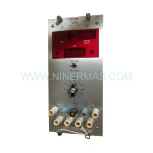
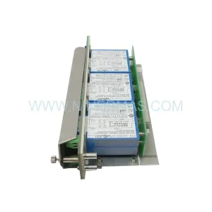
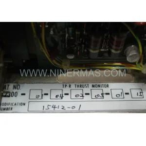
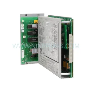
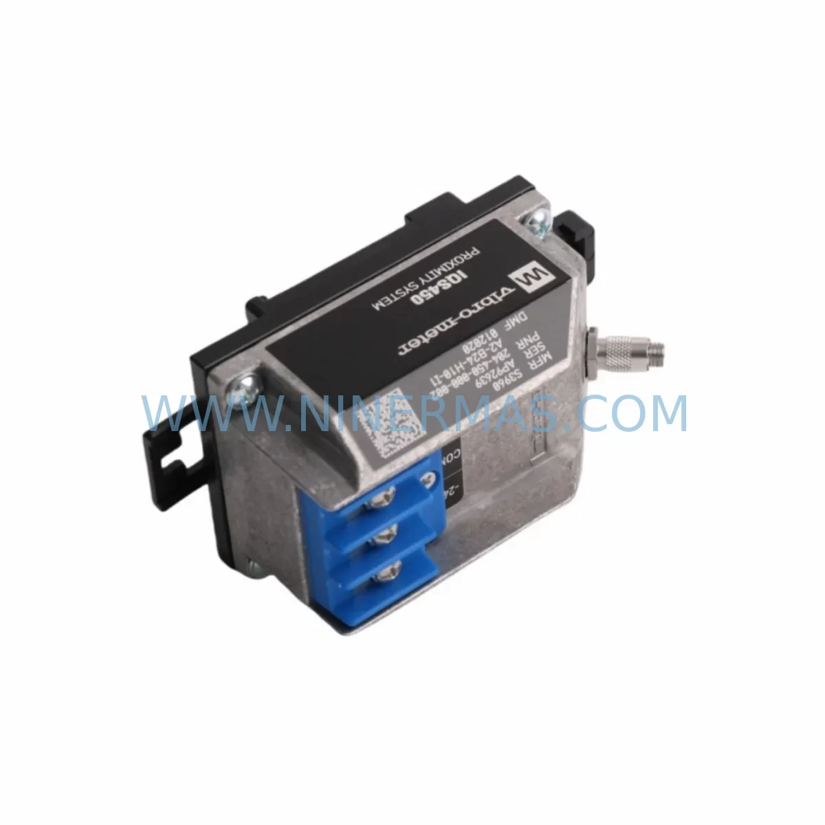
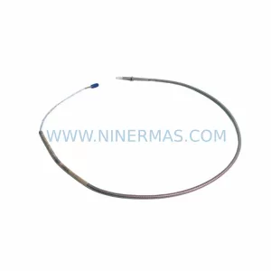
VIBRO-METER 204-450-000-002 Retrofit-Compatible Monitor for Legacy Systems
Verify the part, confirm the platform family, and move straight into quotation with the right commercial details.
RFQ Ready
- SKUIQS450 S3960 204-450-000-002
- CategoryTSI & Rotating Machinery Monitoring
- BrandVibro-Meter
- SupportAvailability, lead time, condition, and shipping coordination
How Buyers Usually Use This Page
- Confirm the exact part number and platform family before sending the quote request.
- Use direct email when quantity, condition, and destination are already defined internally.
- Switch to the broader brand or category archive when you need alternates nearby.
Series Navigation
Move through the most common platform families behind this part.
Product RFQ
Send this part directly for quotation.
Include quantity, required condition, destination country, and target delivery timing. Current reference: VIBRO-METER 204-450-000-002 Retrofit-Compatible Monitor for Legacy Systems with SKU IQS450 S3960 204-450-000-002.
VIBRO-METER 204-450-000-002 Retrofit-Compatible Monitor for Legacy Systems: Smooth Upgrade for IQS450 S3960 Platforms
The VIBRO-METER 204-450-000-002 is a retrofit-compatible signal conditioning and monitoring module engineered for the IQS450 S3960 series platform. As industrial facilities face the growing challenge of maintaining aging vibration monitoring infrastructure, this module serves as a direct replacement and functional upgrade path for legacy VIBRO-METER installations that have reached end-of-life or are no longer supported under active spare parts programs. Whether you are managing a turbine protection system, compressor monitoring rack, or rotating machinery surveillance cabinet, the 204-450-000-002 provides a reliable, field-proven solution that minimizes engineering rework and reduces total retrofit cost.
Designed to integrate within the IQS450 modular architecture, this unit supports the existing backplane interface and rack mounting standard used across the S3960 series. Engineers planning a retrofit or emergency replacement will find that the module preserves the original channel configuration, allowing existing field wiring, terminal blocks, and sensor inputs to remain largely undisturbed during the changeover process.
Upgrade Compatibility Table
| Parameter | Details |
|---|---|
| SKU / Part Number | 204-450-000-002 |
| Compatible Platform | VIBRO-METER IQS450 S3960 Series |
| Backplane Interface | IQS450 standard rack backplane (S3960 compatible) |
| Mounting Standard | Standard IQS450 module slot; no mechanical modification required |
| Communication Compatibility | Compatible with existing IQS450 communication bus; supports legacy protocol continuity |
| Terminal / Wiring | Retains original field terminal layout; existing cable harness reusable in most installations |
| Power Supply Requirement | Verify rack PSU capacity before installation; consult IQS450 power budget documentation |
| Replacement Recommendation | Direct drop-in for discontinued 204-450-000-002 variants; verify firmware revision compatibility |
| Commissioning Notes | Re-address module slot in IQS450 configuration software; validate alarm setpoints post-installation |
| Warranty | 12 Months — covers manufacturing defects and functional failure under normal operating conditions |
Retrofit Planning for Existing Automation Systems
A successful retrofit of the VIBRO-METER 204-450-000-002 within an IQS450 S3960 installation requires careful pre-engineering to avoid unexpected downtime or signal interruption. The planning phase should begin with a full audit of the existing rack assembly, including the IQS450 rack chassis, installed module population, and available slot positions. If the target slot is occupied by a failed or obsolete module, the replacement process is straightforward; however, if the rack layout has been modified over time, slot addressing must be re-verified in the IQS450 configuration utility before the new module is inserted.
Power budget is a critical checkpoint. The IQS450 platform uses a centralized IQS450 power supply module to feed all installed cards. Before adding or replacing the 204-450-000-002, engineers should calculate the total current draw across all populated slots and confirm that the existing PSU has sufficient headroom. In aging systems, the power supply itself may be approaching end-of-life and should be evaluated for concurrent replacement to avoid a secondary failure shortly after the primary retrofit is completed.
Field wiring connected to the 204-450-000-002 typically originates from proximity probes, velocity sensors, or accelerometers mounted on rotating equipment. These signals arrive via IQS450-compatible terminal modules or direct terminal blocks on the front panel. During the retrofit, each channel’s wiring should be documented, labeled, and verified for continuity before the new module is powered. Signal isolation should be confirmed, particularly in installations where signal isolator modules or galvanic separation barriers are used between the field device and the monitoring card.
Communication integration is another area requiring attention. In systems where the IQS450 rack communicates upstream to a DCS, SCADA, or safety system via Modbus RTU, PROFIBUS DP, or a proprietary IQS communication link, the replacement module must be configured to match the original node address and baud rate settings. Any deviation will cause a communication fault at the supervisory level, which may trigger spurious alarms or loss of monitoring data. If the facility is simultaneously migrating from an older communication protocol to a newer standard such as PROFINET or EtherNet/IP, the 204-450-000-002 retrofit can serve as the trigger point for a broader communication architecture upgrade, potentially incorporating a protocol gateway module to bridge legacy and modern networks.
For facilities operating HMI systems tied to the IQS450 platform, the retrofit should include a review of all HMI screen configurations that reference the replaced module’s channel tags. If the IQS450 HMI interface or connected SCADA displays use hardcoded tag addresses, these will need to be updated to reflect any changes in module slot assignment or channel numbering introduced during the retrofit. Failure to update HMI references can result in operators viewing stale or misrouted data after the new module is commissioned.
In cases where the retrofit is part of a broader I/O expansion project — for example, adding new measurement points to an existing turbine monitoring system — the 204-450-000-002 may be installed alongside additional IQS450 I/O expansion modules or keyphasor input cards. These additions require careful slot planning to avoid address conflicts and to ensure that the rack’s total I/O capacity does not exceed the controller’s scan cycle limits. A VIBRO-METER programming cable or USB configuration interface will be needed to access the IQS450 configuration software and complete the module addressing and parameter upload process.
Downtime Control During System Migration
Minimizing production downtime during a VIBRO-METER 204-450-000-002 replacement is achievable with disciplined pre-staging and a structured cutover plan. The most effective approach is to pre-configure the replacement module on the bench before the maintenance window begins. Using the IQS450 configuration software and a VIBRO-METER programming interface cable, the new module can be loaded with the original parameter set — including measurement ranges, alarm thresholds, filter settings, and channel assignments — so that it arrives at the installation site ready for immediate insertion.
During the cutover window, the sequence should follow a defined order: isolate the affected rack slot, remove the failed or obsolete module, insert the pre-configured 204-450-000-002, restore power, and verify communication link status on the IQS450 system display. If the rack supports hot-swap operation, the process can be completed without a full system shutdown, preserving monitoring continuity on all unaffected channels. Where hot-swap is not supported, a coordinated shutdown of the associated machinery protection logic should be arranged with the operations team to prevent spurious trip signals during the module exchange.
After insertion, the commissioning sequence should include a channel-by-channel signal verification using a calibrated signal simulator or by observing live sensor inputs. Alarm setpoints should be confirmed against the original engineering documentation, and any changes to the HMI tag mapping should be validated on the operator display before the maintenance window is closed. A final functional test — including a simulated high-vibration condition to verify trip relay operation — should be completed and documented before the system is returned to normal service. All retrofit activities should be recorded in the facility’s maintenance management system, with the 204-450-000-002 serial number logged for warranty tracking purposes under the 12-month coverage period.
Retrofit Support FAQ
Q1: Is the VIBRO-METER 204-450-000-002 a direct drop-in replacement for the original IQS450 S3960 module?
In most installations, yes. The 204-450-000-002 is designed to fit the standard IQS450 rack slot and maintain compatibility with the existing backplane interface. However, customers should verify the firmware revision of their IQS450 system and confirm that the replacement module’s hardware revision is compatible. Minor wiring adjustments at the terminal block level may be required in installations where field wiring was modified from the original factory configuration.
Q2: What commissioning steps are required after installing the replacement module?
After physical installation, the module must be addressed within the IQS450 configuration software to match the original slot assignment. All measurement parameters — including full-scale ranges, alarm setpoints, and filter configurations — should be re-entered or uploaded from a saved configuration file. Communication link status should be verified at the IQS450 system level, and a live signal check on each channel should be performed before returning the system to service. If the installation includes a connected HMI or SCADA system, tag mapping should be validated to confirm that all display references are correctly routed to the new module.
Q3: Does NINERMAS provide pre-shipment testing for the 204-450-000-002?
Yes. All units supplied by NINERMAS undergo functional testing prior to shipment to verify that the module meets the original manufacturer’s performance specifications. Test records are available upon request. Units are shipped with protective packaging to prevent damage during transit, and each module is covered by a 12-month warranty from the date of delivery, covering manufacturing defects and functional failure under normal operating conditions.
Q4: What is the typical lead time and stock availability for the VIBRO-METER 204-450-000-002?
NINERMAS maintains inventory of the 204-450-000-002 to support urgent replacement requirements. Standard orders are processed and shipped within 3–7 business days. For emergency requirements, expedited shipping options are available. Customers with planned maintenance schedules are encouraged to contact our sales team in advance to confirm stock levels and reserve units. For ongoing spare parts programs or multi-unit procurement, volume pricing and priority allocation can be arranged.
| Product Series | Legacy |
|---|
Catalog Continuation
More Vibro-Meter modules in the catalog.
Use the brand lane to compare nearby part numbers, platform-adjacent modules, and other inquiry-ready listings before sending your final RFQ.
SKU: 204-900-000-011
Vibro-meter 204-900-000-011 Safety-Reliable Vibration Monitor
SKU: 111-412-000-012
Vibro-Meter 111-412-000-012 Retrofit-Compatible Module for VM600
SKU: GSI127 244-127-000-017 A1-B02
Vibro-Meter GSI127 244-127-000-017 A1-B02 Service-Ready Spare Part
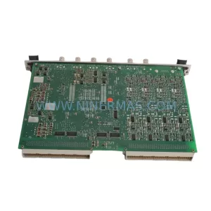
SKU: VM600 MPC4 200-510-041-021
VIBRO-METER VM600 MPC4 200-510-041-021 Safety Machinery Protection
Catalog Continuation
Alternative parts within TSI & Rotating Machinery Monitoring.
Stay inside the same system family when you need substitutes, adjacent modules, or a broader shortlist for procurement review.
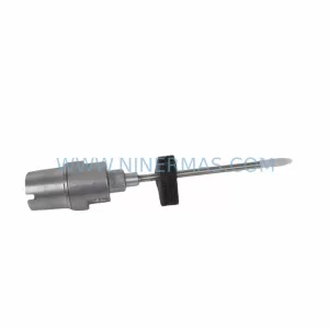
SKU: 21000-28-10-00-167-04-02
Bently Nevada 21000-28-10-00-167-04-02 Retrofit Proximity Probe
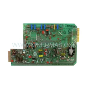
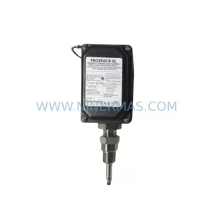
SKU: 330880-16-15-020-01-02
Bently Nevada 330880-16-15-020-01-02 Service-Ready Spare Part
SKU: 330910-00-13-10-02-05
Bently Nevada 330910-00-13-10-02-05 Safety-Reliable Proximity Transducer