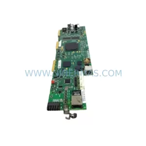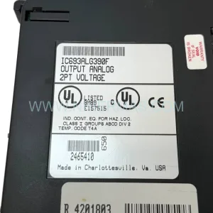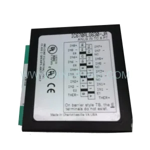
Original Industrial Spare Part
Siemens 6SL3200-0SP06-0AA0 Retrofit Sensor Module Legacy Systems
Verify the part, confirm the platform family, and move straight into quotation with the right commercial details.
RFQ Ready
- SKU6SL3200-0SP06-0AA0
- CategoryPLC & Industrial Automation Modules
- BrandSiemens
- SupportAvailability, lead time, condition, and shipping coordination
How Buyers Usually Use This Page
- Confirm the exact part number and platform family before sending the quote request.
- Use direct email when quantity, condition, and destination are already defined internally.
- Switch to the broader brand or category archive when you need alternates nearby.
Series Navigation
Move through the most common platform families behind this part.
Product RFQ
Send this part directly for quotation.
Include quantity, required condition, destination country, and target delivery timing. Current reference: Siemens 6SL3200-0SP06-0AA0 Retrofit Sensor Module Legacy Systems with SKU 6SL3200-0SP06-0AA0.
Siemens 6SL3200-0SP06-0AA0 Retrofit Sensor Module: Legacy Drive System Compatibility & Smooth Upgrade
The Siemens 6SL3200-0SP06-0AA0 is a cabinet-mounted sensor module designed for the SINAMICS S120 drive platform. In aging production environments where legacy Siemens drive systems have reached end-of-life or where original spare parts are no longer available through standard distribution channels, this module serves as a critical retrofit-compatible replacement that allows facilities to extend the operational life of their existing control infrastructure without committing to a full drive system overhaul.
Industrial plants running older SINAMICS S120 booksize or chassis configurations frequently encounter situations where the original sensor interface module has failed or degraded, causing unplanned downtime on critical axes. The 6SL3200-0SP06-0AA0 addresses this directly by providing a verified drop-in replacement path that preserves existing encoder wiring, drive topology, and motor feedback signal chains. Engineers responsible for retrofit planning can source this module as a like-for-like spare, reducing the engineering effort required to validate a new drive generation against existing motor and mechanical systems.
When integrating this sensor module into a retrofit project, the first step is confirming the existing DRIVE-CLiQ wiring topology. The 6SL3200-0SP06-0AA0 communicates via DRIVE-CLiQ, Siemens’ proprietary drive component network, and must be correctly addressed within the STARTER or TIA Portal commissioning environment. Engineers should verify that the firmware version running on the associated Control Unit CU320-2 or CU310-2 is compatible with the module’s hardware revision before installation. Mismatched firmware can prevent automatic topology recognition and require manual device configuration.
Power supply requirements must also be confirmed during retrofit planning. The sensor module draws its operating voltage from the DRIVE-CLiQ bus, but the cabinet power supply — typically a SITOP PSU100S or equivalent 24 VDC regulated supply — must have sufficient residual capacity to support the additional load when this module is added to an existing drive line-up. In dense cabinet configurations where multiple Motor Modules and Sensor Modules share a common 24 V rail, a load audit is recommended before commissioning.
Terminal wiring adaptation is another key consideration. If the original sensor module used a different connector pinout or encoder interface standard — for example, transitioning from an older SMC10 or SMC20 sensor module cabinet variant — the encoder cable shield termination, differential signal pairs, and supply voltage pins must be re-verified against the 6SL3200-0SP06-0AA0 terminal assignment. Incorrect wiring at the encoder interface can result in speed feedback errors, drive faults (F07801, F07802), or motor runaway conditions during initial commissioning.
For plants operating mixed-generation drive cabinets — for example, a line that includes both newer SINAMICS S120 Combi units and older booksize power sections — the 6SL3200-0SP06-0AA0 can be integrated into the existing DRIVE-CLiQ ring without disrupting the topology of adjacent components such as the Line Module Active or Double Motor Module. The DRIVE-CLiQ ring should be re-scanned after installation to confirm that the new module is correctly identified and that no ghost devices remain from the previous configuration.
HMI screen updates are often overlooked during sensor module replacements. If the plant uses a SIMATIC HMI TP1200 Comfort or similar panel connected to the drive via PROFINET or PROFIBUS DP, the drive parameter set — particularly P0400 (encoder type selection) and P0408 (encoder pulse number) — must be re-entered or restored from a backup project file to ensure that the HMI speed and position displays reflect accurate values after the module swap.
Communication link integrity should be validated after installation. In systems where the SINAMICS S120 communicates upstream to a SIMATIC S7-300 or S7-400 PLC via PROFIBUS DP using a CBE20 communication board, the drive’s station address and baud rate settings must remain unchanged during the sensor module replacement to avoid disrupting the PLC’s cyclic data exchange. If the plant is in the process of migrating from PROFIBUS to PROFINET as part of a broader modernization initiative, this retrofit provides a natural checkpoint to validate the new communication path before committing to a full protocol migration.
Installation space confirmation is essential in retrofit scenarios. The 6SL3200-0SP06-0AA0 is designed for cabinet mounting and requires adequate clearance for DRIVE-CLiQ cable routing and encoder cable entry. In tight cabinet layouts where space has been consumed by additional Braking Resistors, Output Reactors, or supplementary I/O modules, a physical mockup or DIN rail layout review should be completed before ordering to confirm that the module can be installed without relocating adjacent components.
Upgrade Compatibility Table
| Parameter | Details |
|---|---|
| SKU / Part Number | 6SL3200-0SP06-0AA0 |
| Brand | Siemens |
| Series | SINAMICS S120 |
| Module Type | Sensor Module Cabinet-Mounted (SMC) |
| Communication Interface | DRIVE-CLiQ |
| Encoder Interface | HTL / TTL Incremental Encoder |
| Supply Voltage | 24 VDC via DRIVE-CLiQ bus |
| Mounting | Cabinet / DIN Rail |
| Compatible Control Units | CU320-2, CU310-2, CU250S-2 |
| Compatible Power Sections | SINAMICS S120 Booksize, Chassis |
| Commissioning Tool | STARTER, TIA Portal (Startdrive) |
| Replacement For | SMC10, SMC20 (older cabinet sensor variants) |
| Installation Clearance | Confirm DRIVE-CLiQ cable routing space |
| Firmware Compatibility | Verify CU firmware revision before installation |
| Pre-Shipment Testing | Yes — functional and communication verified |
| Warranty | 12 Months |
| Condition | New / Refurbished-to-New Standard |
| Lead Time | In Stock — Ready to Ship |
Retrofit Planning for Existing Automation Systems
A successful retrofit using the 6SL3200-0SP06-0AA0 begins with a structured audit of the existing drive cabinet. Engineers should document the current DRIVE-CLiQ topology, including all connected components such as the Control Unit CU320-2, Active Line Module, Single Motor Module, and any existing Sensor Module Cabinet SMC20 or SMC30 units already in the ring. This topology map becomes the reference baseline for post-installation verification.
Encoder cable integrity is frequently the root cause of sensor module failures in legacy systems. Before installing the replacement module, the existing HTL or TTL encoder cable should be tested for continuity, insulation resistance, and shield integrity. Degraded encoder cables that were masked by a failing sensor module will cause identical fault codes on the new unit if not replaced simultaneously. In many retrofit projects, the encoder cable — often a Siemens MOTION-CONNECT 500 or equivalent shielded cable — is replaced as a standard part of the sensor module swap to eliminate this risk.
For systems where the original drive program was created in an older version of STARTER and has not been migrated to TIA Portal Startdrive, the project file should be backed up and archived before any hardware changes are made. The SIMATIC S7-300 or S7-400 PLC program that interfaces with the drive via PROFIBUS DP should also be backed up, as parameter changes in the drive during commissioning can affect the cyclic data structure expected by the PLC’s drive function blocks.
In multi-axis systems, the sensor module replacement should be planned for one axis at a time to maintain partial production capability during the retrofit window. Adjacent axes using Double Motor Modules or sharing a common DC Link Bus should remain powered and operational where possible, with the affected axis isolated using the drive’s safe torque off (STO) function rather than a full cabinet power-down, to minimize the impact on connected processes.
I/O signal mapping should be reviewed if the plant uses the drive’s onboard digital inputs and outputs for process interlocks. The Terminal Module TM31 or TM15, if present in the cabinet, provides additional I/O expansion and its wiring should be documented before the retrofit to ensure that interlock signals are correctly re-established after the sensor module is replaced and the drive is recommissioned.
Downtime Control During System Migration
Minimizing downtime during a sensor module replacement on a live production line requires careful pre-staging and a disciplined commissioning sequence. The replacement 6SL3200-0SP06-0AA0 should be pre-configured offline where possible, using a laptop running STARTER or TIA Portal Startdrive with a PC Adapter USB A2 or PROFIBUS PC adapter to load the drive parameter set before the module is installed in the cabinet. This approach reduces the time the drive axis is offline to the physical swap and final topology scan, rather than including the full parameter entry process in the downtime window.
The original drive parameter set — including motor data (P0300–P0360), encoder configuration (P0400–P0410), and speed controller gains (P1460, P1462) — should be exported from the existing drive before shutdown using the STARTER upload function or a SIMATIC Memory Card if the control unit supports card-based parameter backup. This backup protects against parameter loss during the hardware swap and provides a restore point if the new module requires re-commissioning from scratch.
During the physical installation, the DRIVE-CLiQ cable should be connected to the new sensor module before the cabinet is powered up, and the encoder cable should be connected and secured with correct shield termination at both the module end and the motor terminal box. Powering up the cabinet with an unconnected DRIVE-CLiQ port can generate topology mismatch faults that require a full drive reset to clear.
After power-up, the control unit will perform an automatic topology recognition scan. Engineers should monitor the STARTER or TIA Portal online view to confirm that the 6SL3200-0SP06-0AA0 appears in the correct position in the DRIVE-CLiQ ring and that no F01375 (topology error) or A01007 (component not recognized) alarms are present. Once topology is confirmed, the motor identification routine (P1910) should be run if the motor data has changed, or skipped if the original motor parameters have been successfully restored from backup.
Final commissioning validation should include a no-load test at low speed to verify encoder feedback direction and signal quality, followed by a loaded test at operating speed to confirm that speed regulation performance meets the original specification. The entire commissioning sequence, from cabinet power-up to production handover, can typically be completed within two to four hours for a single-axis replacement when the pre-staging steps described above have been completed in advance.
Retrofit Support FAQ
Q1: Is the 6SL3200-0SP06-0AA0 a direct replacement for the SMC20 sensor module cabinet?
The 6SL3200-0SP06-0AA0 serves the same functional role as earlier SMC-series cabinet sensor modules in the SINAMICS S120 platform, providing HTL/TTL encoder feedback via DRIVE-CLiQ. However, the physical connector layout and firmware requirements should be verified against your specific drive configuration before installation. Our technical team can confirm compatibility based on your existing drive order number and firmware version.
Q2: What pre-shipment testing is performed on this module?
Each 6SL3200-0SP06-0AA0 unit is tested for DRIVE-CLiQ communication integrity, encoder signal pass-through, and 24 VDC supply function before dispatch. Units are shipped with a test report confirming functional status. All units are covered by a 12-month warranty from the date of delivery.
Q3: Can this module be commissioned using TIA Portal Startdrive, or is STARTER required?
The 6SL3200-0SP06-0AA0 is compatible with both STARTER (V5.4 and later) and TIA Portal Startdrive (V14 and later). If your existing drive project was created in STARTER, it can be migrated to TIA Portal Startdrive using the built-in project migration wizard. We recommend completing the migration before the retrofit to take advantage of TIA Portal’s improved topology editor and online diagnostics.
Q4: What is the lead time and stock availability?
The 6SL3200-0SP06-0AA0 is held in stock and available for immediate dispatch. Standard lead time for international shipments is 3–7 business days depending on destination. For urgent retrofit requirements, expedited shipping options are available. Contact our team to confirm current stock levels and arrange priority dispatch for time-critical maintenance windows.
| Product Series | SINAMICS |
|---|---|
| Country of Origin | DE |
Catalog Continuation
More Siemens modules in the catalog.
Use the brand lane to compare nearby part numbers, platform-adjacent modules, and other inquiry-ready listings before sending your final RFQ.
SKU: 99-10-209 424U0471B-05 424U0511C-05 6SL3120-2TE13-0AA3 (UE41PP) Z376A
Siemens 6SL3120-2TE13-0AA3 Safety-Reliable Double Motor Module
SKU: 6ES7138-4FA02-0AB0
Siemens 6ES7138-4FA02-0AB0 Retrofit-Compatible Power Module
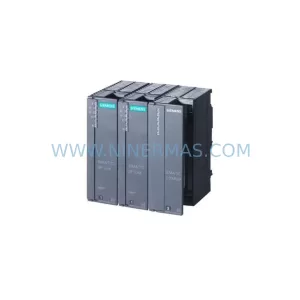
SKU: 6SL3120-2TE13-0AA4 0020-18542 0010-02146 11210-0203RS-001
Siemens 6SL3120-2TE13-0AA4 Service-Ready Spare for Maintenance
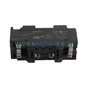
SKU: 6ES7972-4AA02-0XA0
Siemens 6ES7972-4AA02-0XA0 Safety-Reliable PROFIBUS Booster
Catalog Continuation
Alternative parts within PLC & Industrial Automation Modules.
Stay inside the same system family when you need substitutes, adjacent modules, or a broader shortlist for procurement review.
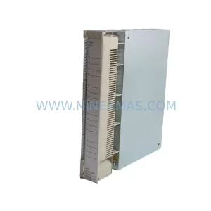
SKU: AI625 3BHT300036R1
ABB AI625 3BHT300036R1 Retrofit Analog Input Module
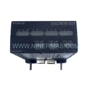
SKU: 3HAC062339-004 3HAC062339-006 lRB7600 3HAC064662-001 DSQC3037 3HAC023195-001
ABB 3HAC062339-004 Service-Ready Spare Part for Industrial Maintenance