Original Industrial Spare Part
Lenze EL9800 EP8GAP71300P6M90XX Retrofit-Compatible Drive for Legacy Systems
Verify the part, confirm the platform family, and move straight into quotation with the right commercial details.
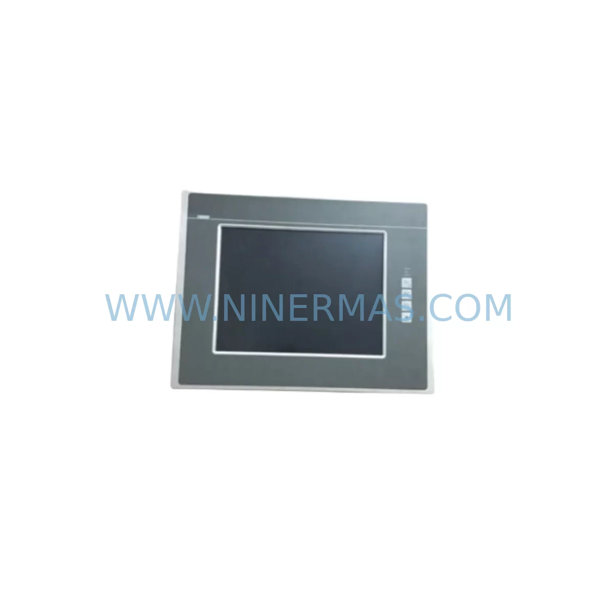
RFQ Ready
- SKUEL9800 EP8GAP71300P6M90XX-00C6901404W
- CategoryPLC & Industrial Automation Modules
- BrandLenze
- SupportAvailability, lead time, condition, and shipping coordination
How Buyers Usually Use This Page
- Confirm the exact part number and platform family before sending the quote request.
- Use direct email when quantity, condition, and destination are already defined internally.
- Switch to the broader brand or category archive when you need alternates nearby.
Series Navigation
Move through the most common platform families behind this part.
Product RFQ
Send this part directly for quotation.
Include quantity, required condition, destination country, and target delivery timing. Current reference: Lenze EL9800 EP8GAP71300P6M90XX Retrofit-Compatible Drive for Legacy Systems with SKU EL9800 EP8GAP71300P6M90XX-00C6901404W.
Lenze EL9800 EP8GAP71300P6M90XX Retrofit-Compatible Drive for Legacy Systems
The Lenze EL9800 EP8GAP71300P6M90XX-00C6901404W is a retrofit-compatible AC frequency inverter engineered for seamless integration into existing Lenze EL9800 series control architectures. As legacy Lenze drive platforms approach end-of-life and original spare parts become increasingly scarce, this unit provides a verified replacement path that preserves existing wiring configurations, motor parameter sets, and PLC communication links — minimising engineering rework and unplanned downtime on the production floor.
Designed for industrial environments where control continuity is non-negotiable, the EL9800 EP8GAP71300P6M90XX-00C6901404W supports direct substitution in applications previously served by discontinued Lenze EL9800 variants. Engineers undertaking a retrofit must confirm power supply voltage range, DC bus compatibility, and terminal block pinout against the original installation drawings before commissioning. The unit’s parameter structure aligns with the Lenze E82 and EL9800 family conventions, allowing parameter migration via the Lenze Global Drive Control (GDC) software tool without full reprogramming of the host PLC.
When integrating this drive into an existing control cabinet, verify available DIN rail space and ventilation clearance. The EL9800 series uses a standard Lenze mounting footprint, but thermal derating must be recalculated if the ambient temperature in the enclosure has changed since the original installation. Confirm that the existing Lenze EMC filter and Lenze line choke upstream of the drive remain rated for the new unit’s input current. If the original installation included a Lenze brake resistor module, verify the resistance value and continuous power rating remain within specification for the replacement drive’s braking chopper threshold.
Upgrade Compatibility Table
| Parameter | Original EL9800 Series | EP8GAP71300P6M90XX-00C6901404W | Retrofit Notes |
|---|---|---|---|
| Supply Voltage | 3-phase 380–480 V AC | 3-phase 380–480 V AC | Confirm incoming supply tolerance ±10% |
| Output Power Class | EL9800 series range | Matched to original frame size | Verify motor nameplate kW rating |
| Control Interface | Lenze AIF / LECOM-A/B | AIF slot compatible | Retain existing Lenze PROFIBUS DP module or CANopen communication card if installed |
| Terminal Wiring | X1 / X2 / X3 terminal blocks | Identical terminal designation | Cross-reference original wiring diagram; check analogue input scaling |
| Mounting | Panel / DIN rail | Panel / DIN rail | Confirm enclosure depth and ventilation gap |
| Communication Protocol | LECOM / PROFIBUS / CANopen | AIF-compatible modules supported | Retain or replace Lenze communication module E82ZAFCC as required |
| Parameter Backup | GDC / keypad upload | GDC compatible | Upload parameter set from original drive before decommissioning |
| Commissioning Tool | Lenze GDC / PC system bus | Lenze GDC / PC system bus | Use Lenze PC system bus adapter E82ZAFPCS for parameter transfer |
| Warranty | — | 12 Months | Covers manufacturing defects; excludes misapplication damage |
Retrofit Planning for Existing Automation Systems
A successful retrofit of the Lenze EL9800 EP8GAP71300P6M90XX-00C6901404W begins with a thorough audit of the existing control cabinet. Start by documenting the current Lenze EL9800 keypad parameter set — either via the GDC software over the PC system bus or by manually recording all modified parameters from the operator panel. This parameter backup is the single most important pre-work step; without it, motor tuning data, ramp times, torque limits, and PLC reference scaling will need to be re-established from scratch during commissioning.
Next, inspect the power section. Confirm that the Lenze line filter E82ZZ series upstream of the drive is rated for the replacement unit’s input current. If the original system used a Lenze output choke E82ZL to protect long motor cables, verify its inductance value remains appropriate. For applications with regenerative braking, check the Lenze brake resistor ERBD series resistance and wattage against the new drive’s braking chopper specifications.
On the communication side, if the legacy system used a Lenze PROFIBUS DP communication module E82ZAFPB inserted into the AIF slot, this module can typically be transferred directly to the replacement drive, preserving the existing PROFIBUS node address and GSD file configuration on the host PLC — whether that PLC is a Siemens S7-300, S7-400, or a third-party controller with PROFIBUS master capability. Similarly, if the original installation used a Lenze CANopen module E82ZAFCC, the node ID and baud rate settings stored in the module’s non-volatile memory will carry over, avoiding the need to reconfigure the CANopen master.
For systems where the EL9800 drive interfaces with a Lenze HMI operator panel EPM-H301 or a third-party HMI via LECOM-A (RS-232) or LECOM-B (RS-485), verify that the HMI screen parameter addresses remain valid for the replacement drive firmware version. Minor firmware differences between production batches of the EL9800 series can shift parameter indices; always cross-reference the parameter list in the replacement unit’s documentation against the HMI project file before going live.
I/O expansion should also be reviewed. If the original drive used a Lenze I/O extension module E82ZAFIO for additional digital or analogue channels, confirm the module’s compatibility with the replacement unit’s AIF interface revision. Analogue input scaling — particularly 0–10 V or 4–20 mA speed reference signals from a DCS or SCADA system — must be verified against the new drive’s input impedance and resolution specifications to avoid reference drift after changeover.
Finally, confirm the physical installation space. The EL9800 series has defined minimum clearances above and below the drive for cooling airflow. If the control cabinet has been modified since the original installation, re-measure the available height and depth. Ensure the replacement unit’s weight is within the mounting rail’s load rating, and that all PE (protective earth) bonding connections are re-established with the correct torque values per the Lenze installation manual.
Downtime Control During System Migration
Minimising production downtime during an EL9800 drive replacement requires a structured changeover plan executed during a scheduled maintenance window. The recommended approach is a staged swap: first, back up the original drive’s parameter set and photograph all terminal wiring connections before disconnecting any cables. Label every wire with its terminal designation using adhesive markers — this step alone eliminates the majority of wiring errors during reinstallation.
With the replacement Lenze EL9800 EP8GAP71300P6M90XX-00C6901404W pre-configured on the bench using GDC software and the backed-up parameter file, the physical swap can be completed in under two hours for a standard panel-mount installation. Restore the communication module (PROFIBUS DP, CANopen, or LECOM adapter) from the original drive, reconnect all power and control terminals per the original wiring diagram, and perform a no-load motor run test before reconnecting the mechanical load.
To protect the original PLC program logic, do not modify any PLC function blocks or HMI screen logic during the drive swap. The goal is a like-for-like hardware replacement that leaves the control software layer untouched. If the PLC uses cyclic PROFIBUS communication with the drive, verify that the drive’s PROFIBUS diagnostic LEDs indicate a healthy data exchange before releasing the machine to production. Keep the original drive on-site for at least one full production shift after the replacement goes live — if an unexpected parameter discrepancy surfaces, the original unit can be reinstalled within minutes while the issue is investigated offline.
For critical continuous-process applications where even a brief stop is unacceptable, consider pre-staging the replacement drive in a parallel test rig to validate motor performance, torque response, and communication behaviour before the live changeover. This approach adds preparation time but reduces the risk of extended unplanned downtime caused by commissioning surprises on the production machine.
Retrofit Support FAQ
Q1: Is the Lenze EL9800 EP8GAP71300P6M90XX-00C6901404W a direct drop-in replacement for my existing EL9800 series drive?
In most cases, yes — provided the power rating, supply voltage, and control interface (AIF module type) match the original installation. Always verify terminal designations and parameter compatibility using the Lenze GDC software before final commissioning. If your original drive used a specific AIF communication module such as a PROFIBUS DP or CANopen card, that module can typically be transferred to the replacement unit.
Q2: What pre-shipment testing is performed on this unit?
Each unit undergoes functional power-on verification and basic output waveform testing prior to dispatch. Units are supplied with original or equivalent packaging to prevent transit damage. A 12-month warranty covers manufacturing defects from the date of shipment. Test records are available upon request for critical infrastructure applications.
Q3: How do I confirm wiring compatibility before installation?
Obtain the original Lenze EL9800 series wiring diagram for your specific variant and cross-reference the terminal block layout (X1 mains input, X2 motor output, X3 control terminals) against the replacement unit’s documentation. Pay particular attention to analogue input terminal polarity, digital input voltage levels (24 V DC PNP/NPN), and the relay output contact ratings. If the original installation used a Lenze keypad or remote operator panel, confirm the RJ45 or SUB-D connector pinout is consistent.
Q4: What is the stock availability and lead time?
We maintain inventory of Lenze EL9800 series components to support urgent maintenance and retrofit projects. Standard orders are processed within 1–3 business days. For large-quantity or project-based requirements, contact our team directly to confirm availability and arrange consolidated shipment. All units are supplied with a 12-month warranty and full traceability documentation.
| Product Series | Legacy |
|---|---|
| Country of Origin | DE |
Catalog Continuation
More Lenze modules in the catalog.
Use the brand lane to compare nearby part numbers, platform-adjacent modules, and other inquiry-ready listings before sending your final RFQ.
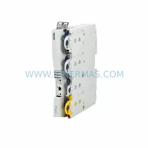
SKU: EL9800 EP8GAP71Y0095M00XX-0000602800G
LENZE EL9800 EP8GAP71Y0095M00XX Retrofit HMI for Legacy Systems
Catalog Continuation
Alternative parts within PLC & Industrial Automation Modules.
Stay inside the same system family when you need substitutes, adjacent modules, or a broader shortlist for procurement review.
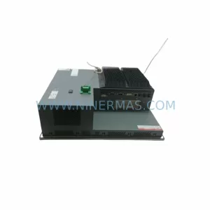
SKU: PFXPP170CA66K00N00
Pro-face PFXPP170CA66K00N00 Service-Ready Spare Part

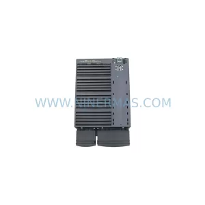
SKU: 6SL3224-0BE32-2UA0
Siemens 6SL3224-0BE32-2UA0 Retrofit PM240 Power Module