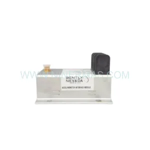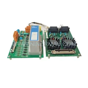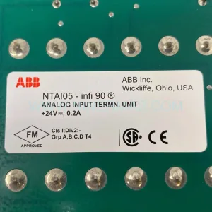
Original Industrial Spare Part
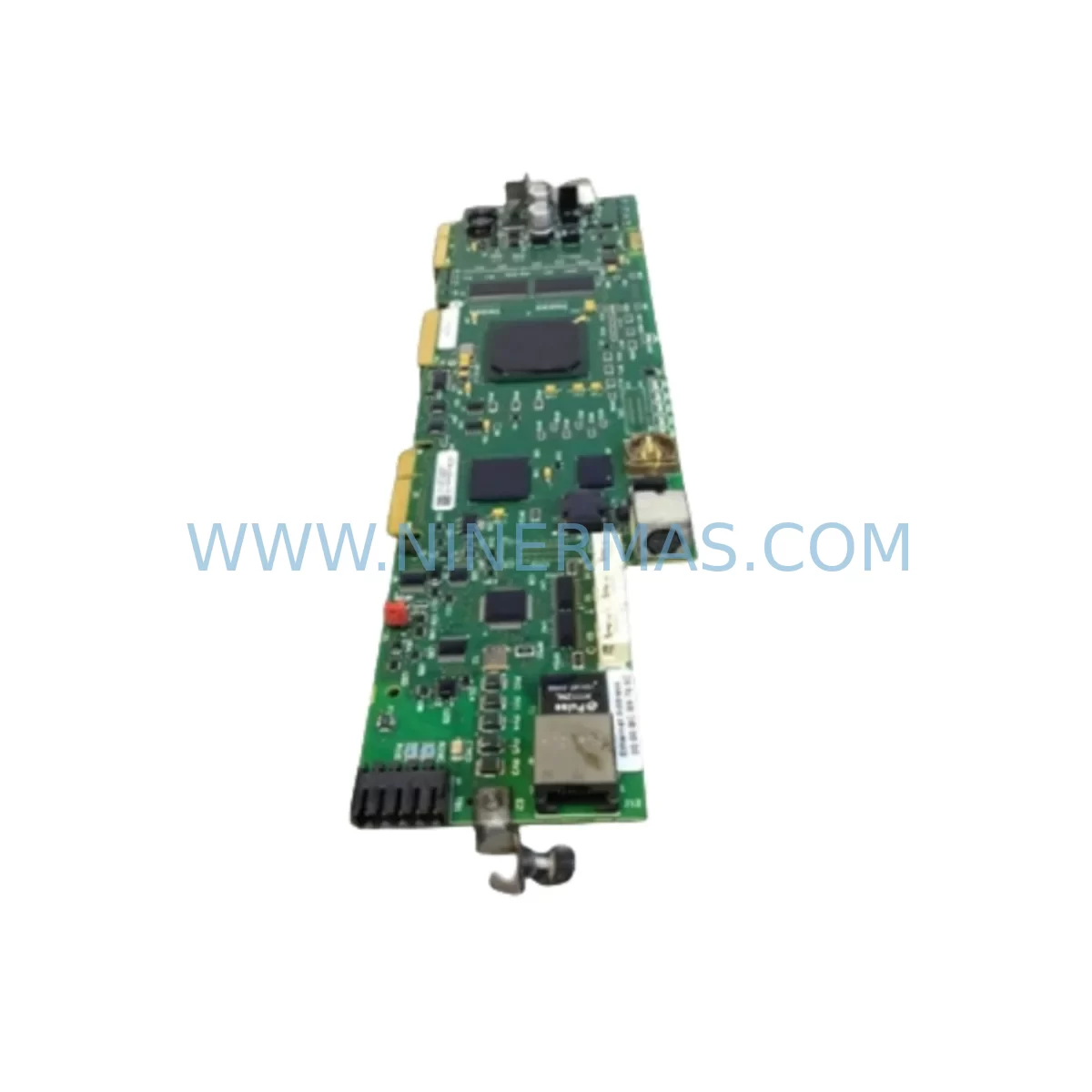
Industrial PN-184930 Retrofit-Compatible Inverter Board
Verify the part, confirm the platform family, and move straight into quotation with the right commercial details.
RFQ Ready
- SKUPN-184930
- CategoryPLC & Industrial Automation Modules
- BrandIndustrial Control Hub
- SupportAvailability, lead time, condition, and shipping coordination
How Buyers Usually Use This Page
- Confirm the exact part number and platform family before sending the quote request.
- Use direct email when quantity, condition, and destination are already defined internally.
- Switch to the broader brand or category archive when you need alternates nearby.
Series Navigation
Move through the most common platform families behind this part.
Product RFQ
Send this part directly for quotation.
Include quantity, required condition, destination country, and target delivery timing. Current reference: Industrial PN-184930 Retrofit-Compatible Inverter Board with SKU PN-184930.
Industrial PN-184930 Retrofit-Compatible Inverter Board: Legacy System Upgrade & Smooth Migration
The PN-184930 is a retrofit-compatible industrial inverter control board engineered to serve as a direct replacement for discontinued inverter drive boards across legacy automation platforms. Whether you are managing a mid-life control cabinet overhaul, restoring a production line after an unexpected board failure, or executing a planned migration away from end-of-life drive hardware, the PN-184930 delivers the electrical compatibility, form-factor precision, and signal integrity required for a low-risk, minimum-downtime changeover.
Designed for integration into existing inverter chassis without structural modification, the PN-184930 supports standard backplane connector pinouts common across multiple drive generations. Engineers responsible for spare-parts lifecycle management will find this board particularly valuable as OEM supply chains for original boards dry up — the PN-184930 is stocked as a long-term supply commitment with a confirmed 12-month warranty on every unit shipped.
Upgrade Compatibility Table
| Parameter | PN-184930 Specification | Retrofit Notes |
|---|---|---|
| Board Form Factor | Standard inverter control PCB | Verify chassis rail spacing before installation |
| Backplane Interface | Multi-pin edge connector | Confirm pin-count matches legacy chassis slot |
| Communication Compatibility | RS-485 / Modbus RTU compatible | Check baud rate and parity settings in drive parameters |
| Power Supply Input | 24 VDC control logic | Validate SMPS-24V output capacity before swap |
| I/O Signal Levels | Digital I/O: 24 VDC; Analog: 0–10 V / 4–20 mA | Re-verify analog reference scaling after replacement |
| Installation Space | Standard DIN-rail / chassis mount | Measure clearance for adjacent modules and cable routing |
| Commissioning Requirement | Parameter re-entry via keypad or PC tool | Back up original drive parameters before removal |
| Replacement Scope | Drop-in for compatible legacy inverter boards | Cross-reference OEM part number against PN-184930 datasheet |
| Warranty | 12-Month Warranty — covers manufacturing defects; includes pre-shipment functional test | |
Retrofit Planning for Existing Automation Systems
A successful PN-184930 retrofit begins well before the board is physically removed from the cabinet. The first step is a thorough audit of the existing control architecture. In most legacy installations, the inverter board sits within a drive chassis that also houses a 24 VDC switching power supply module — confirm that this supply can sustain the inrush current during board initialization before proceeding. If the supply is marginal, a parallel redundant PSU should be staged as part of the upgrade kit.
Terminal wiring is the next critical checkpoint. Legacy inverter boards often use proprietary screw-terminal blocks with non-standard pitch. When installing the PN-184930, re-terminate all control wiring according to the new board’s terminal diagram. Pay particular attention to the analog input reference signal (typically 0–10 V or 4–20 mA from a process controller or PLC analog output module) and the digital run/stop command wiring from the PLC’s digital output card. If the site uses a Modbus RTU communication link over RS-485, verify that the termination resistor on the RS-485 bus is correctly positioned after the board swap — an improperly terminated bus is a common source of intermittent communication faults post-retrofit.
For sites running a programmable logic controller as the master, the PLC program logic referencing the inverter’s frequency setpoint register addresses must be validated against the PN-184930’s Modbus register map. If the legacy board used a different register layout, a minor program revision in the PLC — typically a register offset change — will be required. This is a low-risk edit but must be tested in simulation or during a controlled commissioning window before live production resumes.
HMI screen updates are frequently overlooked during inverter board replacements. If the site’s HMI panel displays drive status, fault codes, or frequency feedback pulled from the inverter via Modbus, the tag addresses and fault code tables in the HMI project may need updating to match the PN-184930’s fault register definitions. Budget time for this during the commissioning phase.
Where the legacy system includes a signal isolator or signal conditioner between the PLC analog output and the inverter frequency reference input, verify that the isolator’s output range is compatible with the PN-184930’s analog input specification. A mismatch here will result in incorrect speed scaling and must be corrected before the drive is released to automatic control.
For multi-axis or multi-drive installations, the PN-184930 retrofit should be sequenced drive-by-drive to maintain partial production capability. Coordinate with the site’s I/O expansion modules and ensure that the PLC’s I/O map remains consistent throughout the phased replacement. If the control cabinet uses a remote I/O rack connected via DeviceNet or Profibus, confirm that the network node address assignments are not disrupted during the physical board swap.
Finally, confirm that the installation space within the drive chassis accommodates the PN-184930’s PCB dimensions and that adequate clearance exists for the ribbon cable or backplane connector to seat fully without mechanical stress. Poor connector seating is a leading cause of intermittent faults in retrofitted drives and should be verified with a gentle pull-test after installation.
Downtime Control During System Migration
Minimizing production downtime during an inverter board replacement requires a structured pre-outage preparation protocol. Before the maintenance window opens, the following actions should be completed: export and archive the full drive parameter set using the drive’s built-in parameter copy function or a PC-based drive commissioning tool; photograph all terminal wiring connections; and confirm that a tested spare PN-184930 board is on-site and has passed the pre-shipment functional test included with every NINERMAS shipment.
During the outage, isolate the drive from mains power and allow the DC bus capacitors to discharge fully — typically 5 minutes after power-off — before touching any internal components. Remove the legacy board, install the PN-184930, and re-terminate all control wiring. Restore power and re-enter the archived parameter set. If the drive supports parameter upload from a keypad memory cartridge or USB adapter, this step can be completed in under 10 minutes.
Before releasing the drive to automatic PLC control, perform a manual jog test at low frequency (5–10 Hz) to confirm correct motor rotation direction and absence of fault codes. Verify that the Modbus communication link is active by checking the PLC’s communication status register. Once manual jog is confirmed, transfer control to the PLC and monitor the first automatic cycle closely. A well-prepared PN-184930 retrofit can be completed within a 2–4 hour planned maintenance window, preserving the original program logic and maintaining field control continuity throughout.
NINERMAS maintains buffer stock of the PN-184930 to support emergency same-day dispatch requirements. All units are subject to pre-shipment functional testing and are covered by a 12-month warranty against manufacturing defects, providing procurement teams with the confidence needed to approve the PN-184930 as a qualified long-term spare.
Retrofit Support FAQ
Q1: Is the PN-184930 a direct drop-in replacement for my existing inverter board?
The PN-184930 is designed to be retrofit-compatible with a range of legacy inverter control boards sharing the same backplane connector standard and PCB form factor. To confirm direct compatibility, provide your existing board’s OEM part number to our technical team at sale@ninermas.com. We will cross-reference against our compatibility database and confirm fit before shipment.
Q2: What commissioning steps are required after installing the PN-184930?
After physical installation, re-enter the drive’s motor parameters (rated voltage, current, frequency, speed) and application parameters (acceleration/deceleration ramps, frequency limits, control mode). If the drive communicates with a PLC via Modbus RTU, verify the station address, baud rate, and parity settings match the PLC’s communication configuration. Perform a manual jog test before returning the drive to automatic control.
Q3: Does the PN-184930 come with a warranty, and is pre-shipment testing included?
Yes. Every PN-184930 unit shipped by NINERMAS carries a 12-month warranty covering manufacturing defects. All units undergo a pre-shipment functional test to verify board-level operation before dispatch. Test records are available upon request for quality-assurance documentation purposes.
Q4: What is the typical lead time, and do you maintain stock for emergency orders?
NINERMAS maintains dedicated buffer stock of the PN-184930 to support both planned procurement and emergency replacement scenarios. Standard orders are dispatched within 1–3 business days. For urgent requirements, contact our team directly to confirm same-day or next-day dispatch availability.
| Product Series | Other series |
|---|
Catalog Continuation
More Industrial Control Hub modules in the catalog.
Use the brand lane to compare nearby part numbers, platform-adjacent modules, and other inquiry-ready listings before sending your final RFQ.
Catalog Continuation
Alternative parts within PLC & Industrial Automation Modules.
Stay inside the same system family when you need substitutes, adjacent modules, or a broader shortlist for procurement review.
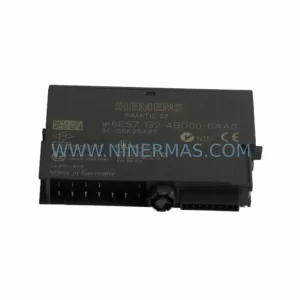
SKU: 6ES7138-4FA02-0AB0
Siemens 6ES7138-4FA02-0AB0 Retrofit-Compatible Power Module
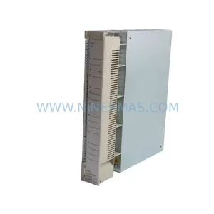
SKU: AI625 3BHT300036R1
ABB AI625 3BHT300036R1 Retrofit Analog Input Module
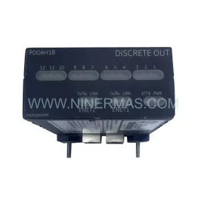
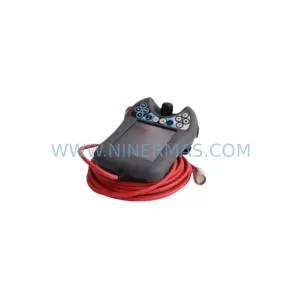
SKU: 3HAC062339-004 3HAC062339-006 lRB7600 3HAC064662-001 DSQC3037 3HAC023195-001
ABB 3HAC062339-004 Service-Ready Spare Part for Industrial Maintenance