Original Industrial Spare Part
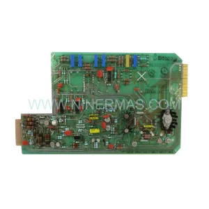
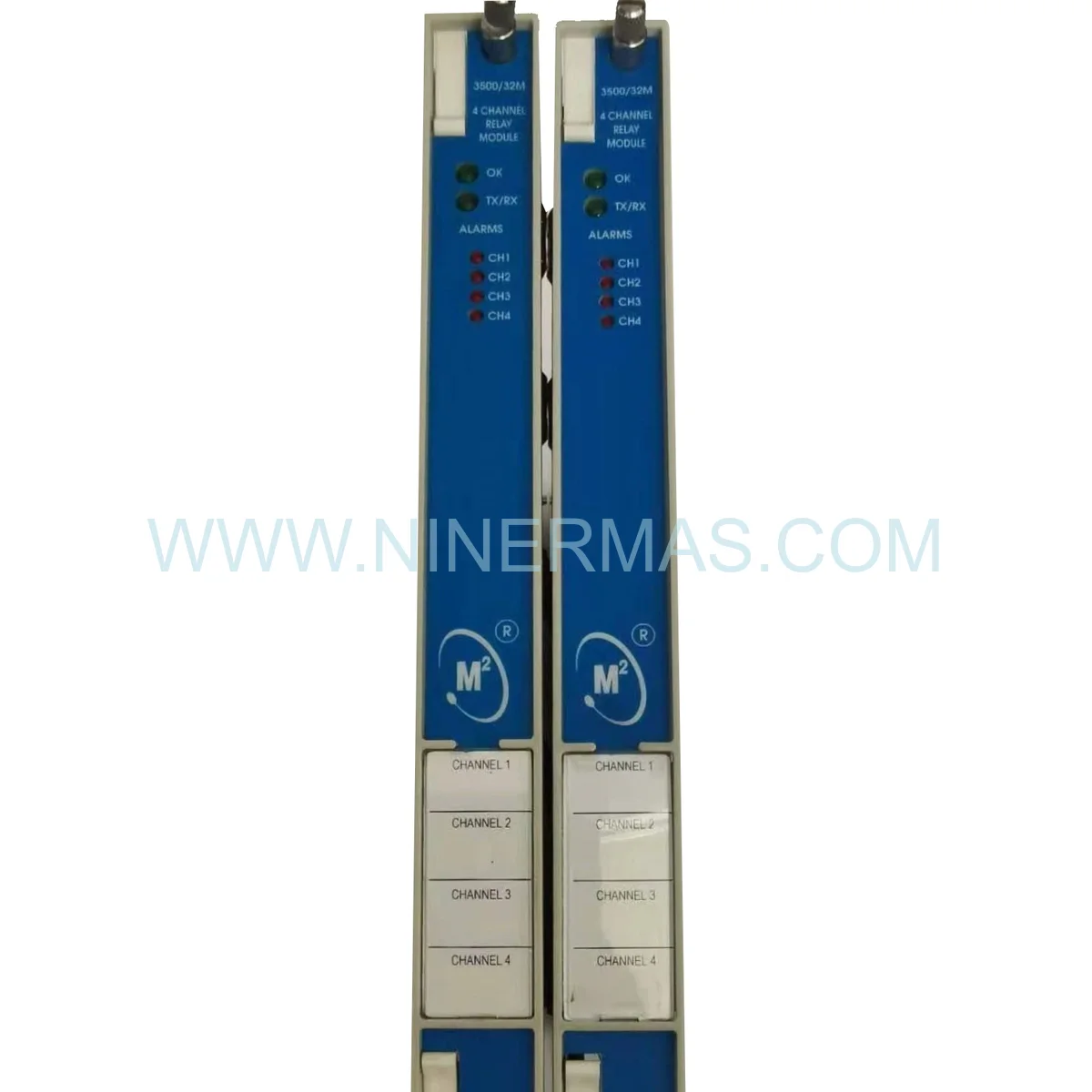
Bently Nevada 3500/32 149986-02 4-Channel Relay Module
Verify the part, confirm the platform family, and move straight into quotation with the right commercial details.
RFQ Ready
- SKU149986-02
- CategoryTSI & Rotating Machinery Monitoring
- BrandBently Nevada
- SupportAvailability, lead time, condition, and shipping coordination
How Buyers Usually Use This Page
- Confirm the exact part number and platform family before sending the quote request.
- Use direct email when quantity, condition, and destination are already defined internally.
- Switch to the broader brand or category archive when you need alternates nearby.
Series Navigation
Move through the most common platform families behind this part.
Product RFQ
Send this part directly for quotation.
Include quantity, required condition, destination country, and target delivery timing. Current reference: Bently Nevada 3500/32 149986-02 4-Channel Relay Module with SKU 149986-02.
Bently Nevada 3500/32 149986-02 Four-Channel Relay Module
The Bently Nevada 3500/32 149986-02 is a four-channel relay output module designed for the 3500 Series machinery protection system. This critical interface module converts digital alarm signals from monitor modules into physical relay contact closures, enabling integration with plant DCS, PLC, and emergency shutdown systems for automated machinery protection and alarm annunciation.
Technical Specifications
- Model Number: 3500/32 (Part Number: 149986-02)
- Series: 3500 Rack Configuration System
- Relay Channels: 4 independent programmable outputs
- Contact Configuration: Form C (SPDT – Single Pole Double Throw)
- Contact Rating: 5A at 30V DC or 250V AC resistive load
- Inductive Load Rating: 2A at 30V DC (L/R = 7ms), 2A at 250V AC (cos = 0.4)
- Contact Material: Silver alloy for low contact resistance and long life
- Switching Voltage: 5-250V AC/DC
- Minimum Switching Load: 10 mA at 5V DC (dry circuit capable)
- Contact Resistance: <100 m © initial, <200 m © end of life
- Mechanical Life: 10 million operations (no load)
- Electrical Life: 100,000 operations at rated load
- Operate Time: <10 ms typical
- Release Time: <5 ms typical
- Isolation Voltage: 1500V AC between relay coil and contacts
- Programmable Logic: AND, OR, NOT, voting (2oo3, 2oo4)
- Alarm Sources: Any monitor module in 3500 rack
- Power Consumption: 4.5W from 3500 rack power supply
- Operating Temperature: -30 °C to +65 °C (-22 °F to +149 °F)
- Storage Temperature: -40 °C to +85 °C (-40 °F to +185 °F)
- Humidity: 5% to 95% non-condensing
- Dimensions: 24.4 mm W — 241.8 mm H — 241.3 mm D (0.96″ — 9.52″ — 9.50″)
- Weight: 0.40 kg (0.88 lbs)
- Slot Position: Any available slot in 3500 rack
Programmable Relay Logic Architecture
The 3500/32 module provides sophisticated alarm processing capabilities beyond simple contact closure:
- Multi-Source Inputs: Each relay can monitor alarm conditions from any combination of monitor modules in the rack, enabling complex protection schemes
- Boolean Logic: Program AND, OR, NOT, and voting logic to create intelligent alarm responses (e.g., trip turbine only if two out of three vibration monitors alarm)
- Alarm Type Selection: Configure each relay to respond to Alert, Danger, or both alarm levels from selected monitors
- Time Delays: Programmable pickup and dropout delays (0-60 seconds) prevent nuisance trips from transient conditions
- Latching/Non-Latching: Select latching mode to maintain relay state until manually reset, or non-latching for automatic reset when alarm clears
- Manual Override: Force relay activation or deactivation via configuration software for testing and commissioning
Application Scenarios
The 3500/32 relay module serves as the critical link between monitoring and protection:
- Emergency Shutdown Systems: Interface vibration monitors with SIS logic solvers to initiate automatic turbine trips when bearing temperatures or vibration levels exceed danger setpoints
- DCS Integration: Provide alarm status to distributed control systems for operator annunciation, trending, and coordinated process shutdown sequences
- PLC Control: Connect to programmable logic controllers for automated responses like starting backup equipment, closing isolation valves, or activating fire suppression
- Alarm Annunciation: Drive horn/light panels, SCADA alarm displays, and remote notification systems to alert operators of machinery faults
- Redundant Protection: Implement 2oo3 voting logic where two out of three vibration monitors must alarm before initiating shutdown, reducing false trips while maintaining safety
- Sequential Shutdown: Coordinate multi-stage shutdown sequences using time-delayed relays (e.g., close steam valve, wait 5 seconds, trip generator breaker)
System Integration & Configuration
The 3500/32 module integrates seamlessly within the 3500 monitoring ecosystem:
- Rack Compatibility: Installs in any available slot of 3500/05 system rack (2-slot through 17-slot configurations)
- Monitor Module Support: Accepts alarm inputs from all 3500 monitor types including 3500/40M, 3500/42M, 3500/45, 3500/46M, 3500/50, 3500/60, 3500/62, and 3500/72M
- Configuration Software: 3500 Rack Configuration Software provides graphical interface for programming relay logic, time delays, and alarm sources
- Multiple Modules: Install multiple 3500/32 modules in single rack for applications requiring more than 4 relay outputs
- Hot-Swap Capability: Not hot-swappable; rack must be powered down for module replacement to prevent inadvertent trips
- Firmware Updates: Field-upgradeable firmware via configuration software for feature enhancements and bug fixes
Installation & Wiring Guidelines
Proper installation ensures reliable relay operation and system safety:
- Terminal Block: Removable screw-terminal connector accepts 12-22 AWG wire; torque to 0.5-0.6 N (4.4-5.3 lb n)
- Contact Wiring: Each relay provides NO (Normally Open), NC (Normally Closed), and COM (Common) terminals for maximum flexibility
- Load Protection: Install RC snubbers (0.1 ¼F + 100 ©) across inductive AC loads to suppress contact arcing and extend relay life
- Flyback Diodes: Connect diodes across DC inductive loads (cathode to positive) to clamp voltage spikes during contact opening
- Wire Routing: Separate relay wiring from low-level signal cables; use shielded cable for runs exceeding 30 meters in high-EMI environments
- Grounding: Connect cable shields to chassis ground at module end only; do not ground at both ends to avoid ground loops
- Safety Circuits: For SIL-rated applications, wire relay contacts in series with certified safety relays per IEC 61508 requirements
Relay Logic Programming Examples
Common protection schemes implemented with the 3500/32 module:
- Simple Alarm: Relay 1 activates when Monitor 1 Channel A exceeds Danger setpoint (1oo1 logic)
- Redundant Voting: Relay 2 activates when any two of three radial vibration monitors alarm (2oo3 voting prevents single-point failures)
- Combined Conditions: Relay 3 activates when bearing temperature AND vibration both exceed Alert levels (AND logic for early warning)
- Backup Protection: Relay 4 activates when primary monitor alarms OR communication to DCS is lost (OR logic ensures fail-safe operation)
- Time-Delayed Trip: Relay activates 10 seconds after alarm condition to allow transient disturbances to clear before initiating shutdown
- Latched Alarm: Relay remains energized after alarm clears, requiring manual reset to acknowledge fault and verify corrective action
Diagnostic Features & Troubleshooting
The 3500/32 module provides comprehensive diagnostic capabilities:
- Status LEDs: Four green LEDs indicate relay energization state; OK LED (amber) confirms module health and backplane communication
- Relay Test Function: Configuration software allows manual activation of each relay for wiring verification and commissioning
- Contact Monitoring: Module tracks relay operation count and contact resistance to predict end-of-life and schedule preventive replacement
- Alarm History: Records last 100 relay activation events with timestamp and triggering alarm source for troubleshooting
- Common Issues: Relay chattering (reduce contact load or add snubber), contacts welded closed (exceeded current rating, replace module), no relay activation (verify alarm source configuration and logic), intermittent operation (inspect terminal connections for looseness)
Safety & Reliability Considerations
Critical factors for deploying relay modules in safety-critical applications:
- Failure Modes: Relays can fail open (safe) or closed (dangerous); design protection logic assuming worst-case failure mode
- Proof Testing: Perform functional testing of relay contacts quarterly per IEC 61511 to detect dangerous undetected failures
- Redundancy: Use dual relay modules with separate wiring to eliminate single points of failure in SIL 2/3 applications
- Contact Degradation: Monitor contact resistance annually; replace module when resistance exceeds 200 m © to prevent voltage drop issues
- Arc Suppression: Always use snubbers or diodes on inductive loads to prevent contact erosion from arcing
- Environmental Protection: Conformal coating on relay coils and contacts provides protection against moisture, dust, and corrosive atmospheres
Compliance & Certifications
The 3500/32 149986-02 meets rigorous international standards:
- Safety: UL 508 Listed, CSA C22.2 No. 14, CE marked per Low Voltage Directive 2014/35/EU
- EMC: EN 61000-6-2 (immunity), EN 61000-6-4 (emissions) for industrial environments
- Functional Safety: Suitable for use in SIL 2 safety instrumented systems per IEC 61508 when configured with appropriate redundancy
- Hazardous Locations: Suitable for Class I Division 2 Groups A, B, C, D when installed per NEC Article 501
- Marine: DNV GL Type Approved for shipboard machinery protection systems
- Environmental: RoHS compliant, REACH registered
Maintenance & Lifecycle Management
Recommended practices for sustained relay performance:
- Inspection Schedule: Annual visual inspection of LED status, terminal connections, and wiring integrity
- Functional Testing: Quarterly activation of each relay using manual test function to verify contact operation
- Contact Resistance: Measure contact resistance every 2 years using low-resistance ohmmeter; replace module if >200 m ©
- Operation Counting: Monitor relay operation count via configuration software; plan replacement at 80% of rated electrical life
- Spare Parts Strategy: Stock one spare 3500/32 module per site for critical applications; typical MTBF exceeds 150,000 hours
- Lifecycle Expectancy: Typical service life 10-15 years depending on switching frequency and load characteristics
Related Products
| Product | Description | Link |
|---|---|---|
| 3500/33 | Bently Nevada 3500 Series 16-Channel Relay Output Module for high-density applications | View Product |
| 3500/42M | Bently Nevada 3500 Proximitor/Seismic Monitor, 4-channel vibration monitoring | View Product |
| 3500/92 | Bently Nevada 3500 Communication Gateway for Modbus/Ethernet integration | View Product |
| Product Series | 3500 Series |
|---|---|
| Country of Origin | US |
Catalog Continuation
More Bently Nevada modules in the catalog.
Use the brand lane to compare nearby part numbers, platform-adjacent modules, and other inquiry-ready listings before sending your final RFQ.

SKU: 21000-16-05-30-026-04-02
Bently Nevada 21000-16-05-30-026-04-02 Safety-Reliable Proximity Probe

SKU: 330881-28-04-70-03-02
Bently Nevada 330881-28-04-70-03-02 Safety-Reliable Proximity Transducer

SKU: 330903-00-17-05-02-00
Bently Nevada 330903-00-17-05-02-00 Retrofit-Compatible NSv Vibration Monitor
Catalog Continuation
Alternative parts within TSI & Rotating Machinery Monitoring.
Stay inside the same system family when you need substitutes, adjacent modules, or a broader shortlist for procurement review.