Original Industrial Spare Part
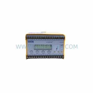
Bently Nevada 3500/33-03-00 16-Channel Relay Output Module
Verify the part, confirm the platform family, and move straight into quotation with the right commercial details.

RFQ Ready
- SKU3500/33-03-00
- CategoryTSI & Rotating Machinery Monitoring
- BrandBently Nevada
- SupportAvailability, lead time, condition, and shipping coordination
How Buyers Usually Use This Page
- Confirm the exact part number and platform family before sending the quote request.
- Use direct email when quantity, condition, and destination are already defined internally.
- Switch to the broader brand or category archive when you need alternates nearby.
Series Navigation
Move through the most common platform families behind this part.
Product RFQ
Send this part directly for quotation.
Include quantity, required condition, destination country, and target delivery timing. Current reference: Bently Nevada 3500/33-03-00 16-Channel Relay Output Module with SKU 3500/33-03-00.
Bently Nevada 3500/33-03-00 16-Channel Relay Output Module
The Bently Nevada 3500/33-03-00 is a 16-channel relay output module engineered for the 3500 Series machinery protection system. This versatile module converts digital alarm signals from monitor modules into physical relay contacts, enabling integration with plant DCS, PLC, annunciator panels, and emergency shutdown systems for comprehensive machinery protection and alarm management.
Technical Specifications
- Model Number: 3500/33-03-00
- Series: 3500 Rack Configuration System
- Relay Channels: 16 independent SPDT (Form C) relays
- Contact Configuration: Single Pole Double Throw (NO, NC, Common)
- Contact Rating: 5A at 30V DC / 250V AC resistive load
- Switching Capacity: 150W DC, 1250 VA AC maximum
- Contact Material: Silver alloy for low contact resistance
- Relay Type: Electromechanical (non-latching)
- Coil Voltage: 24V DC nominal (from 3500 backplane)
- Operating Time: 10 ms typical (energize), 5 ms typical (de-energize)
- Mechanical Life: 10 million operations minimum
- Electrical Life: 100,000 operations at rated load
- Insulation Resistance: >100 M © at 500V DC
- Dielectric Strength: 1500V AC for 1 minute (contact-to-coil)
- Programmable Logic: AND, OR, NOT, voting (2oo3, 2oo4) via configuration software
- Alarm Sources: Any monitor module in 3500 rack (up to 128 alarm inputs)
- Power Consumption: 12W maximum (all relays energized)
- Operating Temperature: -30 °C to +65 °C (-22 °F to +149 °F)
- Storage Temperature: -40 °C to +85 °C (-40 °F to +185 °F)
- Humidity: 5% to 95% non-condensing
- Dimensions: 24.4 mm W — 241.8 mm H — 241.3 mm D (0.96″ — 9.52″ — 9.50″)
- Weight: 0.68 kg (1.5 lbs)
- Slot Position: Any slot in 3500 rack (typically rightmost slots)
Programmable Relay Logic Architecture
The 3500/33 module offers sophisticated alarm processing capabilities beyond simple contact closure:
- Multi-Input Logic: Each relay can be programmed to respond to any combination of up to 128 alarm inputs from monitor modules using AND, OR, NOT Boolean logic
- Voting Logic: Implement 2-out-of-3 (2oo3) or 2-out-of-4 (2oo4) voting schemes for redundant sensor configurations, reducing nuisance trips while maintaining safety integrity
- Alarm Prioritization: Assign relays to specific alarm severity levels (Alert, Danger, Not OK) for staged shutdown sequences
- Time Delays: Configurable pickup and dropout delays (0-60 seconds) filter transient alarms and prevent contact chatter
- Latching Mode: Optional latching behavior requires manual reset after alarm condition clears, ensuring operator acknowledgment
- Fail-Safe Operation: Relays can be configured as normally energized (de-energize on alarm) for fail-safe applications requiring power-to-trip logic
Application Scenarios
The 3500/33 relay module serves as the critical interface between monitoring and control systems:
- Emergency Shutdown Systems: Trigger ESD valves, motor contactors, and fuel shutoff solenoids when vibration or temperature exceeds Danger setpoints in turbomachinery protection
- DCS Integration: Provide hardwired alarm inputs to distributed control systems for annunciation, trending, and automated process responses
- Annunciator Panels: Drive visual and audible alarm panels in control rooms, providing operators with immediate notification of machinery faults
- PLC Interlock Logic: Interface with programmable logic controllers to implement complex interlock sequences (e.g., prevent compressor startup if lube oil pressure is low)
- Redundant Trip Systems: Implement SIL-rated safety instrumented functions using 2oo3 voting logic on redundant vibration sensors
- Remote Alarm Transmission: Activate radio telemetry units or cellular modems to notify maintenance personnel of critical alarms at unmanned facilities
System Integration & Configuration
The 3500/33 module integrates seamlessly within the 3500 monitoring ecosystem:
- Rack Compatibility: Installs in any slot of 3500/05 system rack (2-slot through 17-slot configurations)
- Multiple Modules: Up to 4 relay modules per rack provide 64 total relay outputs for complex alarm schemes
- Configuration Software: 3500 Rack Configuration Software provides graphical interface for programming relay logic, setpoints, and time delays
- Alarm Mapping: Drag-and-drop interface maps monitor module alarms to relay outputs with visual logic diagram
- Simulation Mode: Test relay logic offline before downloading to module, verifying correct operation without energizing field devices
- Hot-Swap Capability: Not hot-swappable; rack must be powered down for module replacement to prevent spurious trips
Installation & Wiring
Proper installation ensures reliable alarm actuation and long relay life:
- Terminal Blocks: Removable screw-terminal blocks accept 12-22 AWG wire; torque to 0.5-0.6 N (4.4-5.3 lb n)
- Wire Sizing: Use 14 AWG minimum for loads >3A; derate for ambient temperatures >40 °C
- Contact Protection: Install RC snubbers (0.1 ¼F + 100 ©) across inductive loads (solenoids, contactors) to suppress arcing and extend contact life
- Load Isolation: Use relay contacts to switch low-voltage control circuits; avoid switching high-voltage power circuits directly
- Grounding: Connect relay common terminals to appropriate ground reference (typically DCS/PLC common); avoid ground loops
- Cable Routing: Separate relay wiring from high-voltage AC power cables; use shielded cable for runs exceeding 100 meters in high-EMI environments
- Fusing: Install 5A fast-blow fuses on each relay output for overcurrent protection
Diagnostic Features & Troubleshooting
The 3500/33 module provides comprehensive diagnostic capabilities:
- Status LEDs: 16 individual green LEDs indicate relay energization state for rapid visual troubleshooting
- Module OK LED: Amber LED confirms module is powered, configured, and communicating with rack
- Software Diagnostics: Configuration software displays real-time relay states, alarm inputs, and logic evaluation results
- Relay Test Function: Manually energize/de-energize individual relays via software for field wiring verification
- Alarm History: Module logs relay activation timestamps and durations for maintenance analysis
- Common Issues: Relay chatter (reduce pickup/dropout delay or add contact suppression), contacts welded (reduce inrush current or replace module), no relay operation (verify alarm logic configuration and monitor module status)
Safety & Reliability Considerations
Deploying relay modules in safety-critical applications requires careful design:
- Fail-Safe Design: Configure relays as normally energized (de-energize to trip) so power loss or module failure causes safe shutdown
- Redundancy: Use multiple relay modules with diverse alarm logic to achieve SIL 2 or SIL 3 safety integrity levels
- Proof Testing: Perform annual relay contact resistance measurements and trip testing per IEC 61508 requirements
- Contact Degradation: Monitor relay operation counts; replace module after 100,000 operations at rated load or 10 years, whichever comes first
- Arc Suppression: Always use snubbers on inductive loads to prevent contact erosion and extend electrical life
- Environmental Protection: Install rack in NEMA 12 or IP54 enclosure minimum to protect relays from dust and moisture
Advanced Configuration Examples
Leverage programmable logic for sophisticated alarm management:
- Staged Shutdown: Relay 1 = Alert OR Danger (annunciate), Relay 2 = Danger only (trip), providing operators time to respond before automatic shutdown
- Redundant Sensors: Relay = (Sensor A Danger) AND (Sensor B Danger), preventing spurious trips from single sensor failures
- Voting Logic: Relay = 2oo3 (Sensor 1, Sensor 2, Sensor 3), requiring two of three sensors to alarm before tripping for high-reliability applications
- Maintenance Bypass: Relay = (Vibration Danger) AND NOT (Maintenance Mode), allowing sensor testing without triggering shutdown
- Conditional Alarms: Relay = (Bearing Temp High) AND (Lube Oil Pressure Low), identifying compound fault conditions
Compliance & Certifications
The 3500/33-03-00 meets rigorous international standards:
- Safety: UL 508 Listed, CSA C22.2 No. 142, CE marked per Low Voltage Directive 2014/35/EU
- EMC: EN 61000-6-2 (immunity), EN 61000-6-4 (emissions) for industrial environments
- Functional Safety: Suitable for use in SIL 2 safety instrumented functions per IEC 61508 when properly configured
- Hazardous Locations: Suitable for Class I Division 2 Groups A, B, C, D when installed per NEC Article 501
- Marine: DNV GL Type Approved for shipboard machinery monitoring and alarm systems
- Environmental: RoHS compliant, REACH registered
Maintenance & Lifecycle Management
Recommended practices for sustained reliability:
- Inspection Schedule: Annual visual inspection of LED status, terminal connections, and relay operation counts
- Contact Resistance Testing: Measure contact resistance annually using milliohm meter; replace module if resistance exceeds 50 m ©
- Functional Testing: Quarterly trip testing of critical shutdown relays to verify correct operation and response time
- Spare Parts Strategy: Stock one spare relay module per site for critical applications; typical MTBF exceeds 150,000 hours
- Configuration Backup: Save relay logic configuration files to non-volatile storage after commissioning for rapid replacement
- Lifecycle Expectancy: Typical service life 10-15 years depending on switching frequency and load characteristics
Related Products
| Product | Description | Link |
|---|---|---|
| 3500/32 | Bently Nevada 3500 Series 4-Channel Relay Output Module | View Product |
| 3500/42 | Bently Nevada 3500 Series Proximitor/Seismic Monitor, 4-channel vibration monitoring | View Product |
| 3500/15 | Bently Nevada 3500 Series Power Supply Module for rack systems | View Product |
| Product Series | 3500 Series |
|---|---|
| Country of Origin | US |
Catalog Continuation
More Bently Nevada modules in the catalog.
Use the brand lane to compare nearby part numbers, platform-adjacent modules, and other inquiry-ready listings before sending your final RFQ.

SKU: 21000-16-05-30-026-04-02
Bently Nevada 21000-16-05-30-026-04-02 Safety-Reliable Proximity Probe

SKU: 330881-28-04-70-03-02
Bently Nevada 330881-28-04-70-03-02 Safety-Reliable Proximity Transducer

SKU: 330903-00-17-05-02-00
Bently Nevada 330903-00-17-05-02-00 Retrofit-Compatible NSv Vibration Monitor
Catalog Continuation
Alternative parts within TSI & Rotating Machinery Monitoring.
Stay inside the same system family when you need substitutes, adjacent modules, or a broader shortlist for procurement review.