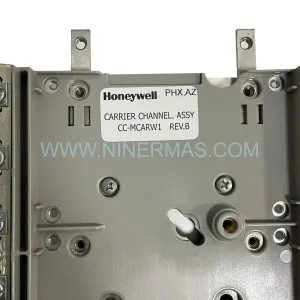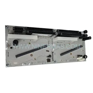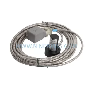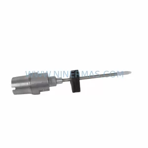
Original Industrial Spare Part
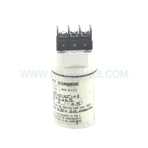
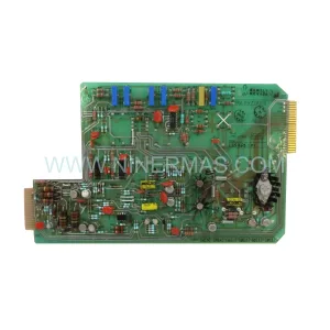
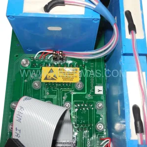
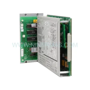
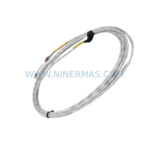
Bently Nevada 330102-00-80-10-11-00 Retrofit Proximity Probe Safety Module
Verify the part, confirm the platform family, and move straight into quotation with the right commercial details.
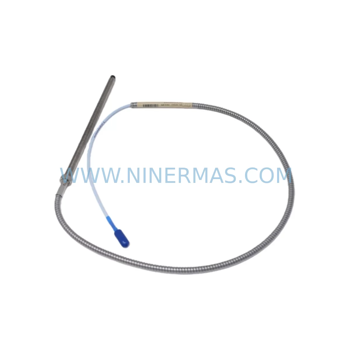
RFQ Ready
- SKU330102-00-80-10-11-00
- CategoryTSI & Rotating Machinery Monitoring
- BrandBently Nevada
- SupportAvailability, lead time, condition, and shipping coordination
How Buyers Usually Use This Page
- Confirm the exact part number and platform family before sending the quote request.
- Use direct email when quantity, condition, and destination are already defined internally.
- Switch to the broader brand or category archive when you need alternates nearby.
Series Navigation
Move through the most common platform families behind this part.
Product RFQ
Send this part directly for quotation.
Include quantity, required condition, destination country, and target delivery timing. Current reference: Bently Nevada 330102-00-80-10-11-00 Retrofit Proximity Probe Safety Module with SKU 330102-00-80-10-11-00.
Bently Nevada 330102-00-80-10-11-00 Retrofit Proximity Probe Safety Module: Legacy System Compatibility & Smooth Upgrade
The Bently Nevada 330102-00-80-10-11-00 is a ruggedized proximity probe safety module engineered for continuous vibration monitoring in critical rotating machinery applications. As legacy Bently Nevada 3300 Series systems approach end-of-life and spare parts become increasingly scarce, this module serves as a direct retrofit-compatible replacement, enabling maintenance engineers and automation teams to extend the operational life of existing monitoring infrastructure without requiring a full platform migration.
Whether you are managing a turbine control panel, a compressor monitoring rack, or a legacy DCS-integrated vibration protection loop, the 330102-00-80-10-11-00 is designed to slot into existing installations with minimal disruption. Its ruggedized construction ensures reliable performance in harsh industrial environments including high-vibration, high-temperature, and chemically aggressive plant conditions.
Upgrade Compatibility Table
| Parameter | Details |
|---|---|
| SKU / Part Number | 330102-00-80-10-11-00 |
| Series | Bently Nevada 3300 Series |
| Module Function | Ruggedized Proximity Probe Safety Module |
| Mounting / Installation | Compatible with standard 3300 Series rack and backplane |
| Signal Interface | Proximity probe (eddy-current) input, 4–20 mA / voltage output |
| Communication Compatibility | Compatible with legacy 3300 Series communication architecture |
| Replacement Recommendation | Direct replacement for discontinued 330102 series variants |
| Commissioning Notes | Verify probe gap voltage, transducer sensitivity, and OK relay logic before energizing |
| Power Supply Requirement | Confirm rack power capacity; compatible with 3300 Series power supply modules |
| Warranty | 12-Month Warranty included |
Retrofit Planning for Existing Automation Systems
Integrating the 330102-00-80-10-11-00 into an existing plant environment requires careful pre-engineering to ensure a smooth transition. Before installation, engineers should audit the current rack configuration, including the Bently Nevada 3300/16 rack or 3300/20 rack, to confirm available slot positions and backplane compatibility. The module must be seated in a slot that supports proximity probe input channels — not all rack positions are interchangeable in mixed-module configurations.
Power budget verification is a critical first step. The existing Bently Nevada 3300/05 power supply or equivalent must have sufficient headroom to support the additional module load. In aging installations, power supply modules are often operating near capacity, and adding a replacement safety module without a load audit can trigger nuisance trips or supply instability.
Terminal wiring should be mapped against the original loop drawings. The 330102-00-80-10-11-00 uses standard Bently Nevada terminal block conventions, but field wiring from the 3300 XL 8mm proximity transducer or 3300 XL 11mm proximity transducer must be verified for correct polarity, shield grounding, and cable routing. Improper shielding is a common source of noise interference that can cause false OK relay dropout during commissioning.
For systems that also include Bently Nevada 3500/42M velocity and acceleration modules or 3500/45 position monitor modules in the same rack, module address configuration must be reviewed to avoid channel conflicts. The system rack address DIP switches or software configuration (depending on firmware revision) must be set correctly before the module is powered up.
Where the existing installation includes a Bently Nevada 3300/55 keyphasor module, the phase reference signal must remain uninterrupted during the swap. Loss of keyphasor signal during a hot-swap attempt can cause the entire rack to enter a fault state, triggering unnecessary machinery trips. A planned outage window with pre-staged replacement hardware is strongly recommended.
HMI screen updates may also be required. If the plant uses a System 1 Evolution software platform or a third-party SCADA system integrated via Modbus or OPC-DA, the channel tag mapping should be verified post-installation to ensure that vibration trend data, alarm setpoints, and danger limits are correctly reflected in the operator display. Failure to update HMI tag assignments is a frequent oversight that leads to masked alarms after a module replacement.
For installations migrating from older 3300 Series hardware to the newer Bently Nevada 3500 Series platform, the 330102-00-80-10-11-00 can serve as an interim solution to maintain monitoring continuity while the full migration is planned and budgeted. This approach avoids forced emergency replacements and allows engineering teams to schedule the 3500 Series cutover during a planned turnaround.
Downtime Control During System Migration
Minimizing unplanned downtime is the primary concern when replacing safety-critical monitoring modules in live production environments. The 330102-00-80-10-11-00 is supplied pre-tested and bench-verified, which significantly reduces the risk of receiving a defective unit that requires a second outage for re-replacement.
Before the maintenance window opens, the replacement module should be staged alongside all required tools: a calibrated gap voltage meter, the original loop drawings, the rack configuration printout, and a laptop loaded with the appropriate Bently Nevada configuration software. Having these resources ready before the outage begins is the single most effective way to compress total downtime.
The original program logic — including alarm setpoints, danger limits, time delays, and OK relay configurations — should be documented and exported from the existing system before the old module is removed. This ensures that if the new module requires re-configuration from factory defaults, all parameters can be re-entered accurately without relying on memory or incomplete records.
During the physical swap, the field wiring should be photographed before disconnection. Terminal labels in aging installations are frequently faded or missing, and a photographic record eliminates ambiguity during reconnection. After the new module is seated and wired, a cold-start verification sequence should be performed: confirm OK relay status, verify gap voltage is within the linear range (typically –10 VDC ± 2 VDC for standard 3300 Series probes), and check that the vibration channel is reading a plausible baseline value before releasing the machinery for restart.
Post-installation, a 24-hour trend review is recommended to confirm that the new module is tracking vibration signatures consistently with historical baseline data. Any unexpected step-change in vibration readings should be investigated before the system is returned to normal monitored operation.
Retrofit Support FAQ
Q: Is the 330102-00-80-10-11-00 a direct drop-in replacement for other 330102 series variants?
A: The 330102-00-80-10-11-00 is a specific configuration within the 330102 family. The suffix codes define cable length, connector type, and temperature rating. Before ordering, confirm that the suffix configuration matches your existing installation requirements. In many cases, the -00-80-10-11-00 configuration is interchangeable with adjacent variants, but this should be verified against the original loop documentation.
Q: What commissioning steps are required after installation?
A: After physical installation, verify probe gap voltage, confirm OK relay energization, check channel vibration reading against a known reference, and validate alarm and danger setpoints against the original configuration record. If the system is integrated with a DCS or SCADA platform, confirm that the channel tag is correctly mapped and that trend data is being logged normally.
Q: How do I confirm wiring compatibility with my existing terminal blocks?
A: The 330102-00-80-10-11-00 uses standard Bently Nevada terminal block conventions. Compare the terminal assignment diagram in the module datasheet against your existing loop drawings. Pay particular attention to shield grounding points and the polarity of the transducer power supply lines. If the existing wiring uses a junction box or field barrier, verify that the barrier is rated for the transducer drive voltage.
Q: What is the warranty and supply lead time?
A: All units are supplied with a 12-month warranty covering manufacturing defects and functional performance. Stock availability is maintained to support urgent replacement requirements. Units are shipped after passing outgoing functional test verification. Contact our team for current lead time and inventory status.
| Product Series | 3301 |
|---|---|
| Country of Origin | US |
Catalog Continuation
More Bently Nevada modules in the catalog.
Use the brand lane to compare nearby part numbers, platform-adjacent modules, and other inquiry-ready listings before sending your final RFQ.
SKU: 330881-16-00-205-00-02
Bently Nevada 330881-16-00-205-00-02 Retrofit 3300 XL
SKU: 330910-00-13-50-02-00
Bently Nevada 330910-00-13-50-02-00 Safety-Reliable Proximity Module
SKU: 22810-00-10-10-02
Bently Nevada 22810-00-10-10-02 Retrofit Proximity Probe
Catalog Continuation
Alternative parts within TSI & Rotating Machinery Monitoring.
Stay inside the same system family when you need substitutes, adjacent modules, or a broader shortlist for procurement review.