Original Industrial Spare Part
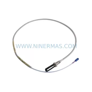
Bently Nevada 330500-04-02 Retrofit-Compatible Piezo-Velocity Sensor
Verify the part, confirm the platform family, and move straight into quotation with the right commercial details.
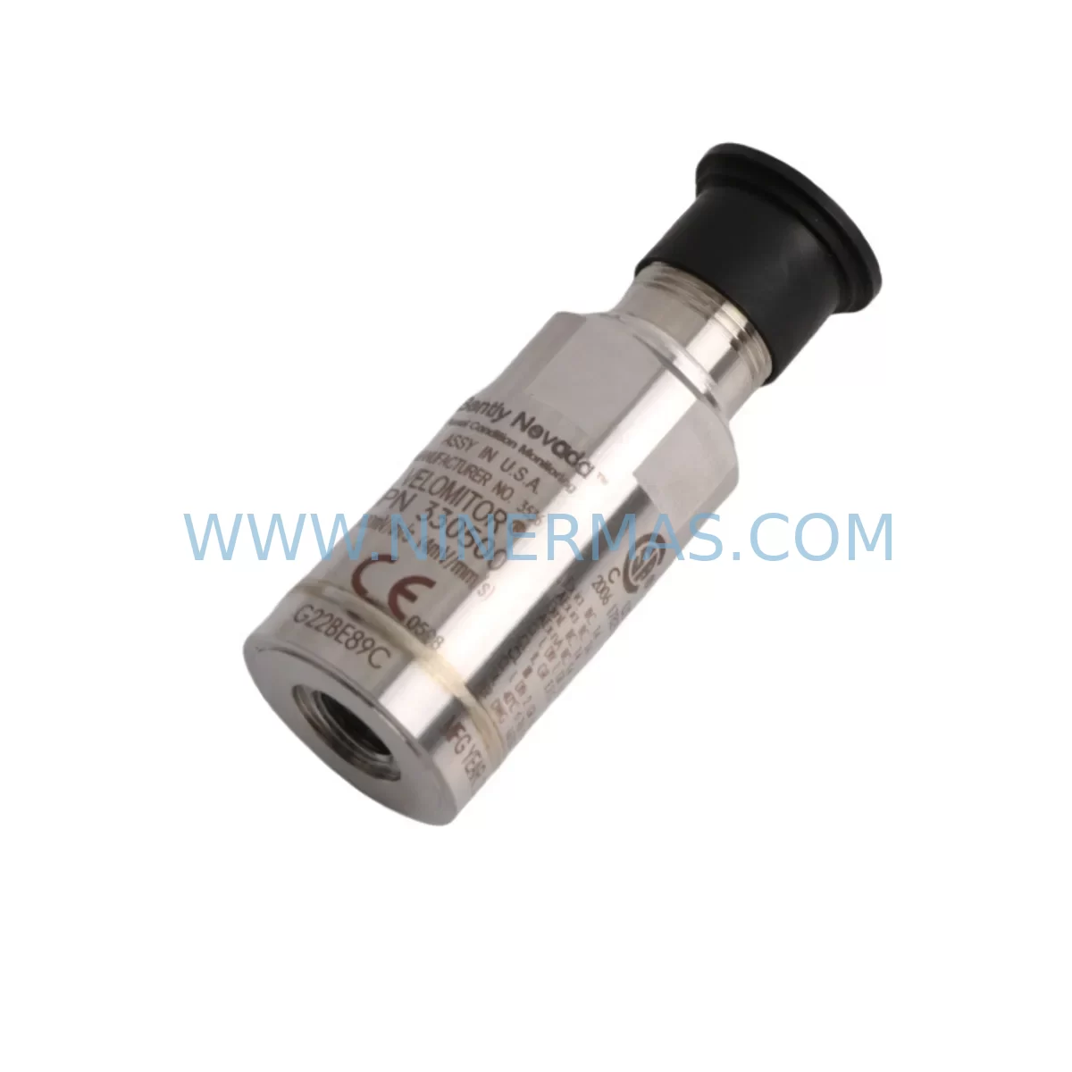
RFQ Ready
- SKU330500-04-02
- CategoryTSI & Rotating Machinery Monitoring
- BrandBently Nevada
- SupportAvailability, lead time, condition, and shipping coordination
How Buyers Usually Use This Page
- Confirm the exact part number and platform family before sending the quote request.
- Use direct email when quantity, condition, and destination are already defined internally.
- Switch to the broader brand or category archive when you need alternates nearby.
Series Navigation
Move through the most common platform families behind this part.
Product RFQ
Send this part directly for quotation.
Include quantity, required condition, destination country, and target delivery timing. Current reference: Bently Nevada 330500-04-02 Retrofit-Compatible Piezo-Velocity Sensor with SKU 330500-04-02.
Bently Nevada 330500-04-02 Retrofit-Compatible Piezo-Velocity Sensor for Legacy System Modernization
The Bently Nevada 330500-04-02 is a ruggedized piezo-velocity sensor module engineered for continuous vibration monitoring in rotating machinery applications. As legacy Bently Nevada 3300 Series systems approach end-of-life and spare parts become increasingly scarce, the 330500-04-02 remains one of the most sought-after retrofit-compatible components for engineers tasked with sustaining aging predictive maintenance infrastructure. Whether you are replacing a failed unit on a critical compressor train, upgrading a turbine monitoring cabinet, or migrating from an obsolete 3300/16 rack to a modern System 1 platform, this sensor module provides the mechanical and electrical compatibility required for a smooth, low-risk transition.
NINERMAS maintains verified inventory of the 330500-04-02 with full functional testing prior to shipment and a 12-month warranty covering manufacturing defects and operational failure under normal service conditions.
Upgrade Compatibility Table
| Parameter | 330500-04-02 Specification | Retrofit Notes |
|---|---|---|
| Sensor Type | Ruggedized Piezo-Velocity | Direct replacement for standard 330500 series variants |
| Output Signal | Velocity (mV/mm/s or mV/in/s) | Verify monitor input card scaling before swap |
| Connector Interface | 2-pin MIL-spec connector | Confirm mating connector on existing field cable |
| Mounting | Stud-mount, 1/4-28 UNF thread | Check bearing housing thread condition before installation |
| Operating Temperature | -50°C to +121°C | Suitable for high-temperature turbine and compressor environments |
| Communication Compatibility | Analog 4–20 mA / voltage output | Compatible with 3300 Series monitors and System 1 input modules |
| Rack / Backplane | 3300/16 and 3500 Series compatible | Confirm rack slot assignment and channel address in configuration software |
| Replacement Recommendation | Drop-in for 330500-04-00, 330500-04-01 | No firmware change required; recalibrate after installation |
| Commissioning Focus | Zero-speed check, full-speed vibration baseline | Log baseline readings before declaring system ready |
| Warranty | 12 Months | Covers manufacturing defects and operational failure under normal use |
Retrofit Planning for Existing Automation Systems
Successful integration of the 330500-04-02 into an existing machinery protection system begins well before the sensor arrives on site. Engineers should start by auditing the current rack configuration — particularly whether the installation uses a Bently Nevada 3300/16 rack or has already been partially migrated to a 3500 Series rack. The two platforms share physical sensor compatibility but differ significantly in monitor card addressing, configuration software, and communication architecture.
On the monitor side, the corresponding Bently Nevada 3300/15 Velocity Monitor or 3500/42M Velocity Monitor must be verified for correct input scaling. If the existing monitor card has been configured for a different sensor sensitivity (e.g., 100 mV/in/s vs. 200 mV/in/s), the alert and danger setpoints will read incorrectly after sensor replacement. This is one of the most common commissioning errors during retrofit projects and can be avoided by pulling the existing configuration file from the System 1 software before the outage window begins.
Field wiring is equally critical. The 330500-04-02 uses a 2-pin MIL-spec connector, and the mating connector on the existing field cable should be inspected for corrosion, pin damage, and correct polarity. In many legacy installations, field cables have been in service for 15 to 20 years and may require replacement with new Bently Nevada 330130 extension cables or equivalent shielded twisted-pair cable to maintain signal integrity. Cable routing should keep sensor leads separated from high-voltage power conductors to prevent electromagnetic interference from corrupting vibration readings.
For installations where the control cabinet also houses a Bently Nevada 3300/20 Power Supply or a 3500/15 Power Supply Module, the engineer should confirm that the power supply has sufficient capacity to support the additional sensor load, particularly if the retrofit involves adding new measurement points to a previously under-instrumented machine train. Power budget calculations should account for all active monitor cards, communication gateway modules, and any 3500/92 Communication Gateway units used to bridge the monitoring system to a DCS or SCADA platform via Modbus or Ethernet/IP.
If the plant’s control system includes a Honeywell Experion PKS or Emerson DeltaV DCS, the vibration data from the 330500-04-02 is typically routed through the Bently Nevada communication gateway rather than directly to the DCS I/O cards. Verifying that the gateway’s tag database reflects the new sensor channel — including engineering units, full-scale range, and alarm thresholds — is a mandatory step before returning the machine to service. HMI faceplate displays should also be reviewed to confirm that the vibration trend screens are pulling data from the correct historian tag after any channel reassignment.
In applications where the 330500-04-02 is being installed as part of a broader I/O expansion — for example, adding vibration monitoring to a previously unmonitored auxiliary pump or fan — the engineer must also confirm that the 3500 Series rack has available slot capacity and that the 3500/22M Transient Data Interface or equivalent module is configured to capture startup and shutdown transient data for the new measurement point. Transient data capture is particularly valuable during the first several run cycles after a retrofit, as it allows the reliability team to establish a new vibration baseline and detect any installation-related anomalies before they develop into failures.
Downtime Control During System Migration
Minimizing unplanned downtime is the primary concern for any maintenance team undertaking a sensor retrofit on a running production line. For the 330500-04-02, the recommended approach is to complete all pre-work — configuration backup, cable inspection, spare parts staging, and permit preparation — during the period before the scheduled outage window. The sensor itself can typically be replaced in under 30 minutes by an experienced technician, but the surrounding verification tasks — monitor reconfiguration, signal loop check, and vibration baseline acquisition — require additional time that must be budgeted into the outage plan.
Before breaking any connections, the existing program logic in the safety system or DCS should be placed in bypass mode for the affected measurement points to prevent spurious shutdowns during the swap. If the plant uses a Triconex Safety System or similar SIL-rated platform with hardwired trips from the Bently Nevada monitors, the bypass procedure must follow the site’s management of change (MOC) process and be documented in the work order. After the new sensor is installed and the signal loop has been verified, the bypass should be removed and the system returned to normal protective mode before the machine is restarted.
Post-installation, the first 30 minutes of machine operation should be monitored continuously, with a technician or engineer present at the System 1 workstation to observe vibration trends in real time. Any reading that deviates significantly from the pre-retrofit baseline should be investigated immediately — common causes include incorrect sensor orientation, loose mounting stud, or a wiring error at the field connector. Catching these issues during the initial run-up prevents a second unplanned outage and protects the machine from operating with degraded vibration protection.
NINERMAS ships all 330500-04-02 units with a pre-shipment functional test report. This documentation confirms that the sensor output was verified against a calibrated reference standard before dispatch, reducing the risk of receiving a non-conforming unit and the associated downtime cost of a repeat repair cycle.
Retrofit Support FAQ
Q1: Is the 330500-04-02 a direct drop-in replacement for the 330500-04-00 and 330500-04-01?
Yes. The 330500-04-02 is mechanically and electrically compatible with earlier -04-00 and -04-01 variants. The mounting thread, connector type, and output signal characteristics are identical. After installation, recalibrate the associated monitor card and acquire a new vibration baseline before returning the machine to service.
Q2: What commissioning steps are required after replacing the sensor?
After physical installation, perform a signal loop check from the sensor connector to the monitor card input. Verify that the monitor is reading a plausible vibration level at zero speed (typically near zero mV). Confirm alert and danger setpoints in the System 1 configuration software. During the first machine run-up, log vibration readings at multiple speed points and compare against the historical baseline for that measurement location.
Q3: Can NINERMAS supply the 330500-04-02 with a certificate of conformance and test report?
Yes. All units shipped by NINERMAS include a pre-shipment functional test report and a certificate of conformance upon request. Documentation is available in English and can be provided in PDF format for inclusion in your maintenance management system records.
Q4: What is the warranty coverage and what does it include?
NINERMAS provides a 12-month warranty on the 330500-04-02 from the date of shipment. The warranty covers manufacturing defects and operational failure under normal service conditions. It does not cover damage resulting from incorrect installation, overvoltage, mechanical impact, or operation outside the specified environmental limits. Warranty claims are processed within 5 business days of receipt of the returned unit.
| Product Series | 3305 |
|---|---|
| Country of Origin | US |
Catalog Continuation
More Bently Nevada modules in the catalog.
Use the brand lane to compare nearby part numbers, platform-adjacent modules, and other inquiry-ready listings before sending your final RFQ.
SKU: 21000-16-10-00-103-04-02
Bently Nevada 21000-16-10-00-103-04-02 Service-Ready Spare Part
SKU: 330905-00-06-10-01-00
Bently Nevada 330905-00-06-10-01-00 Safety-Reliable Proximity Transducer
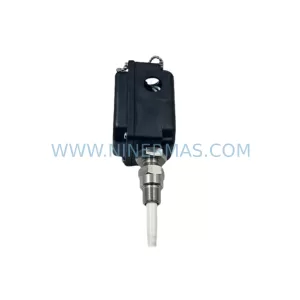
SKU: 330881-28-00-050-03-02
Bently Nevada 330881-28-00-050-03-02 Service-Ready Spare Part
Catalog Continuation
Alternative parts within TSI & Rotating Machinery Monitoring.
Stay inside the same system family when you need substitutes, adjacent modules, or a broader shortlist for procurement review.
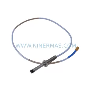
SKU: 330876-02-10-00-00
Bently Nevada 330876-02-10-00-00 Ruggedized Proximity Probe
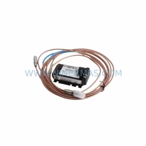
SKU: 913-402-000-013
VIBRO-METER EA402 913-402-000-013 Retrofit Signal Conditioner
SKU: 330704-000-026-50-02-CN
Bently Nevada 330704-000-026-50-02-CN Spare Part