Original Industrial Spare Part
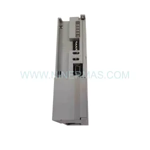
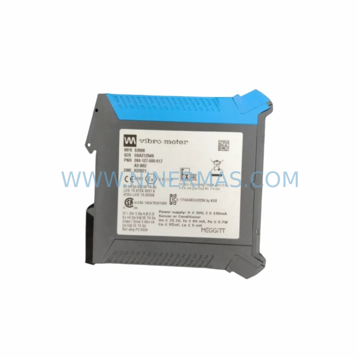
VIBRO-METER 244-127-000-017 A2-B02 Retrofit Vibration Monitor
Verify the part, confirm the platform family, and move straight into quotation with the right commercial details.
RFQ Ready
- SKU244-127-000-017 A2-B02
- CategoryTSI & Rotating Machinery Monitoring
- BrandVibro-Meter
- SupportAvailability, lead time, condition, and shipping coordination
How Buyers Usually Use This Page
- Confirm the exact part number and platform family before sending the quote request.
- Use direct email when quantity, condition, and destination are already defined internally.
- Switch to the broader brand or category archive when you need alternates nearby.
Series Navigation
Move through the most common platform families behind this part.
Product RFQ
Send this part directly for quotation.
Include quantity, required condition, destination country, and target delivery timing. Current reference: VIBRO-METER 244-127-000-017 A2-B02 Retrofit Vibration Monitor with SKU 244-127-000-017 A2-B02.
VIBRO-METER 244-127-000-017 A2-B02 Retrofit Vibration Monitor: Legacy System Compatibility & Smooth Upgrade
The VIBRO-METER 244-127-000-017 A2-B02 is a precision vibration monitoring module engineered for industrial rotating machinery protection and condition monitoring. As legacy vibration monitoring systems reach end-of-life and original spare parts become increasingly scarce, the 244-127-000-017 A2-B02 serves as a critical retrofit-compatible replacement that allows plant engineers and maintenance teams to extend the operational life of existing control architectures without committing to a full system overhaul.
Designed within the VIBRO-METER A2-B02 series platform, this module integrates seamlessly into existing rack-mounted monitoring systems. Its signal conditioning circuitry, terminal wiring layout, and backplane interface are engineered to match the footprint and electrical characteristics of the original installed unit, dramatically reducing the engineering effort required during a planned or emergency replacement. Whether you are managing a turbine protection panel, a compressor monitoring cabinet, or a pump condition monitoring rack, the 244-127-000-017 A2-B02 delivers the measurement accuracy and relay output reliability that critical rotating equipment demands.
For facilities operating aging distributed control systems (DCS) or safety instrumented systems (SIS) where vibration monitoring channels feed directly into trip logic, the availability of a verified replacement module like the 244-127-000-017 A2-B02 is essential to maintaining system integrity. Procurement teams managing spare parts lifecycle programs will find this module a reliable stock item to hold against unplanned outages, particularly where the original manufacturer has discontinued active production of earlier A2-series variants.
Upgrade Compatibility Table
| Parameter | Details |
|---|---|
| SKU / Part Number | 244-127-000-017 A2-B02 |
| Series | VIBRO-METER A2-B02 Series |
| Module Function | Vibration Monitoring & Signal Conditioning |
| Backplane Interface | Compatible with A2-series rack backplane; verify slot addressing before installation |
| Terminal Wiring | Matches legacy terminal block layout; confirm sensor cable shielding and grounding scheme |
| Power Supply Requirement | Verify rack power capacity (typically ±15 VDC or 24 VDC depending on chassis generation) |
| Communication Compatibility | Analog 4–20 mA output and relay contacts; confirm DCS input card compatibility |
| Installation Space | Standard A2-series module form factor; confirm available rack slot before ordering |
| Replacement Recommendation | Direct replacement for discontinued A2-B02 variants; functional verification recommended after installation |
| Commissioning Notes | Re-confirm alarm and trip setpoints in monitoring software after module swap; validate relay output wiring to SIS/DCS |
| Warranty | 12-Month Warranty from date of shipment |
Retrofit Planning for Existing Automation Systems
Successful integration of the 244-127-000-017 A2-B02 into an existing monitoring system begins with a thorough pre-retrofit audit. Maintenance engineers should start by documenting the current rack configuration, noting which slots are occupied by companion modules such as the VIBRO-METER speed monitoring modules, keyphasor signal conditioners, and proximity probe driver cards that share the same chassis. In many installations, the A2-B02 vibration channel module operates alongside dedicated thrust position monitoring modules and temperature monitoring cards within the same protection rack, and any physical disturbance to the rack during module replacement must account for the sensitivity of these adjacent channels.
Before removing the legacy module, engineers should capture all current alarm and trip setpoint values from the monitoring system’s configuration software or front-panel display. Where the system interfaces with a DCS via 4–20 mA analog signals, the receiving DCS analog input card should be verified for input range compatibility. In installations where the vibration monitoring rack communicates with a PLC or safety controller via hardwired relay contacts, the relay output wiring diagram must be reviewed to ensure the replacement module’s relay configuration matches the original — particularly the normally-open or normally-closed contact state used for the trip circuit.
Power supply capacity within the rack is another critical checkpoint. The rack’s internal power supply module — often a dedicated monitoring system power supply card — must have sufficient headroom to support the 244-127-000-017 A2-B02 without causing voltage droop on adjacent channels. In older installations where the power supply module itself may be approaching end-of-life, it is advisable to assess whether a power supply replacement should be scheduled concurrently with the vibration module swap to avoid a secondary failure shortly after the retrofit.
For installations where the vibration monitoring system feeds data to an HMI or SCADA system, the engineering team should verify that the HMI display configuration — including tag names, engineering unit scaling, and alarm visualization — remains valid after the module replacement. In some cases, the HMI configuration may reference module-specific parameters that require updating if the replacement module has a slightly different output characteristic or scaling factor. Similarly, where a programming cable or configuration interface is used to set module parameters, the engineering team should confirm that the configuration tool version is compatible with the replacement module’s firmware.
I/O expansion considerations are also relevant in facilities planning a broader control system upgrade. If the retrofit of the 244-127-000-017 A2-B02 is part of a larger migration from a legacy monitoring platform to a modern condition monitoring system, the team should evaluate whether additional I/O modules, signal isolators, or protocol converters will be required to bridge the legacy sensor wiring to the new platform. In such scenarios, signal isolation barriers are commonly used to protect the new system’s input circuits from ground loops introduced by the existing field wiring.
Downtime Control During System Migration
Minimizing unplanned downtime is the primary concern when replacing a vibration monitoring module on a running production asset. For critical rotating machinery — turbines, compressors, pumps — where the vibration monitoring channel feeds directly into a trip circuit, the replacement procedure must be carefully coordinated with the operations team to ensure that the machine is either safely shut down or that a temporary bypass is authorized and documented in accordance with the site’s management of change (MOC) procedure.
Where a hot-swap or online replacement is not possible, the recommended approach is to schedule the module replacement during a planned maintenance window. Prior to the window, the replacement 244-127-000-017 A2-B02 module should be bench-tested to verify basic functionality — confirming that the module powers up correctly, that relay outputs respond to simulated input signals, and that the analog output is within specification. This pre-shipment functional verification, combined with the 12-month warranty coverage provided with every unit, gives maintenance teams confidence that the replacement module will perform correctly from the moment it is installed.
During the replacement, the original program logic in the connected PLC or safety controller should not be modified. The goal is to restore the vibration monitoring channel to its original functional state as quickly as possible, preserving all existing trip logic, alarm setpoints, and interlock configurations. After the module is installed and wired, a loop check should be performed by applying a known vibration signal at the sensor input and verifying that the correct analog output value and relay state are observed at the DCS or safety controller. This end-to-end verification step is essential before the bypass is removed and the trip circuit is re-armed.
For facilities managing multiple aging vibration monitoring channels across a large machinery protection system, maintaining a small inventory of verified replacement modules such as the 244-127-000-017 A2-B02 is a cost-effective strategy for reducing mean time to repair (MTTR) and avoiding the extended lead times associated with sourcing discontinued spare parts on the open market.
Retrofit Support FAQ
Q1: Is the 244-127-000-017 A2-B02 a direct drop-in replacement for my existing A2-series vibration module?
In most cases, yes. The 244-127-000-017 A2-B02 is designed to be compatible with the A2-B02 series rack and backplane interface. However, we recommend verifying the terminal wiring layout, power supply voltage, and relay output configuration against your existing installation drawings before proceeding. Our technical team can assist with compatibility confirmation if you provide your existing module’s part number and rack configuration details.
Q2: What commissioning steps are required after installing the replacement module?
After physical installation, you should re-confirm all alarm and trip setpoints in the monitoring system configuration software, perform a loop check by applying a known input signal and verifying the analog output and relay state, and validate the relay output wiring to your DCS or safety controller. If the system includes an HMI, verify that all display tags and scaling values remain correct. A full functional test should be completed before removing any bypass and re-arming the trip circuit.
Q3: Do you provide pre-shipment testing, and what warranty is included?
Yes. Every 244-127-000-017 A2-B02 unit is functionally tested before shipment to verify power-up, analog output accuracy, and relay output operation. Each unit is supplied with a 12-month warranty from the date of shipment, covering manufacturing defects and functional failures under normal operating conditions. Warranty support includes technical assistance for installation and commissioning issues.
Q4: What is your typical lead time and stock availability?
We maintain stock inventory of the 244-127-000-017 A2-B02 to support urgent replacement requirements. Standard lead time for in-stock units is 3–7 business days for international shipment. For large quantity orders or scheduled maintenance programs requiring multiple units, please contact our sales team to discuss availability and delivery scheduling.
| Product Series | Other series |
|---|
Catalog Continuation
More Vibro-Meter modules in the catalog.
Use the brand lane to compare nearby part numbers, platform-adjacent modules, and other inquiry-ready listings before sending your final RFQ.
SKU: 913-402-000-013
VIBRO-METER EA402 913-402-000-013 Retrofit Signal Conditioner
SKU: 204-900-000-011
Vibro-meter 204-900-000-011 Safety-Reliable Vibration Monitor
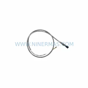
SKU: 111-412-000-012
Vibro-Meter 111-412-000-012 Retrofit-Compatible Module for VM600
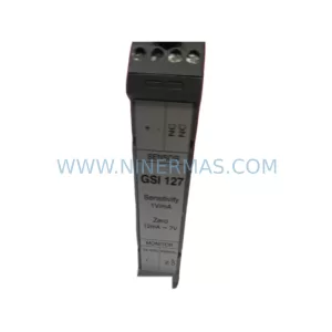
SKU: GSI127 244-127-000-017 A1-B02
Vibro-Meter GSI127 244-127-000-017 A1-B02 Service-Ready Spare Part
Catalog Continuation
Alternative parts within TSI & Rotating Machinery Monitoring.
Stay inside the same system family when you need substitutes, adjacent modules, or a broader shortlist for procurement review.
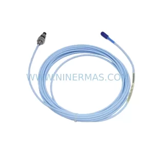
SKU: 330106-05-30-50-12-CN
Bently Nevada 330106-05-30-50-12-CN Service-Ready Spare Part for Industrial Maintenance
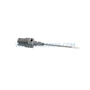
SKU: 21000-16-05-40-049-04-02
Bently Nevada 21000-16-05-40-049-04-02 Proximity Probe Housing
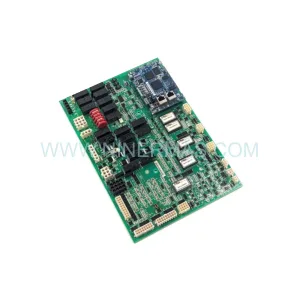
SKU: IS200AEPAH1AHD(IS215AEPAH1CA)
GE IS200AEPAH1AHD Mark VI Control Layer Module (GE) Original Spare Part RFQ