Original Industrial Spare Part
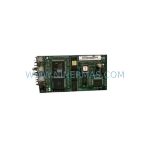
YOKOGAWA AAP135-S53 Retrofit-Compatible I/O Module for Legacy Systems
Verify the part, confirm the platform family, and move straight into quotation with the right commercial details.
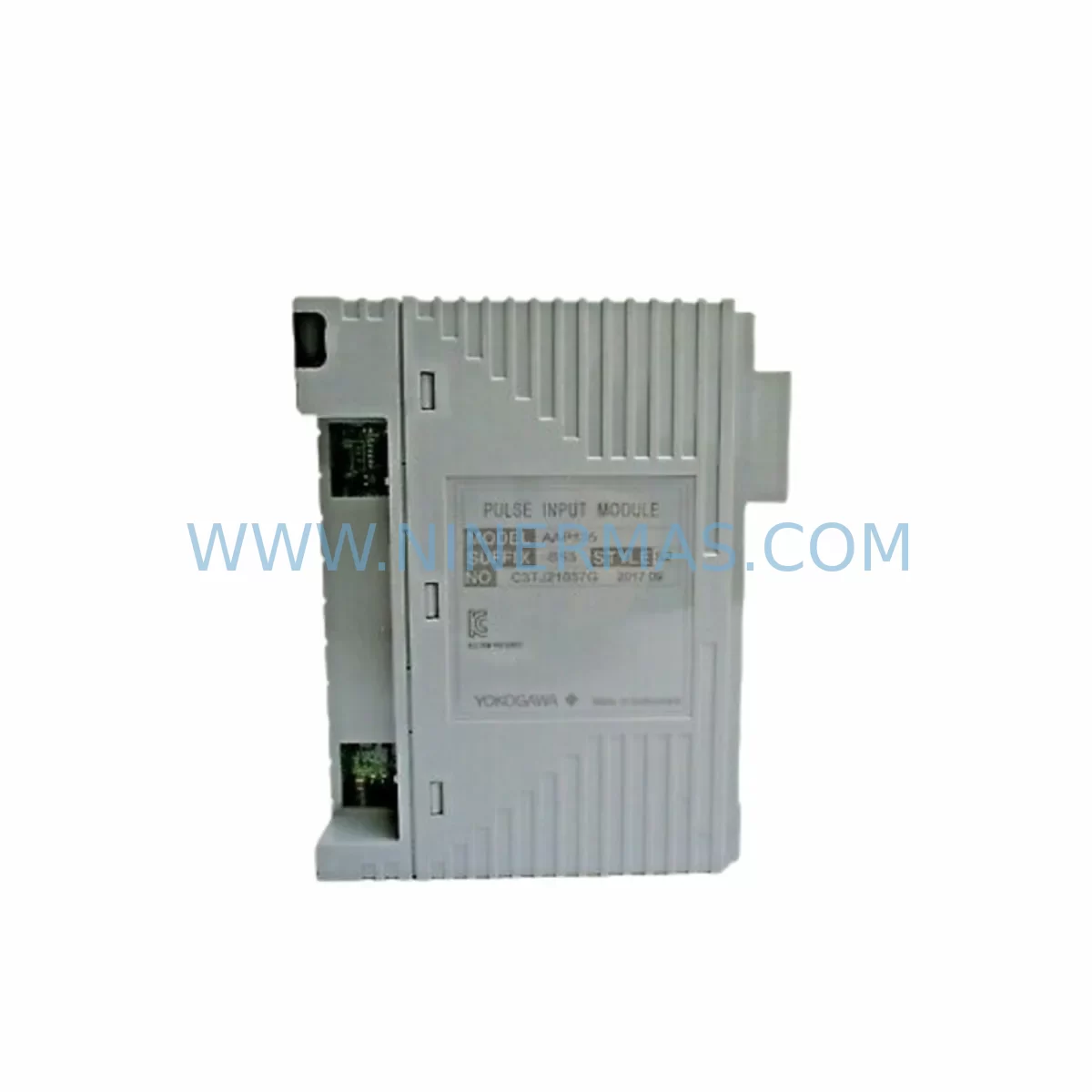
RFQ Ready
- SKUAAP135-S53
- CategoryDCS Distributed Control Systems
- BrandYokogawa
- SupportAvailability, lead time, condition, and shipping coordination
How Buyers Usually Use This Page
- Confirm the exact part number and platform family before sending the quote request.
- Use direct email when quantity, condition, and destination are already defined internally.
- Switch to the broader brand or category archive when you need alternates nearby.
Series Navigation
Move through the most common platform families behind this part.
Product RFQ
Send this part directly for quotation.
Include quantity, required condition, destination country, and target delivery timing. Current reference: YOKOGAWA AAP135-S53 Retrofit-Compatible I/O Module for Legacy Systems with SKU AAP135-S53.
YOKOGAWA AAP135-S53 Retrofit-Compatible I/O Module for Legacy Systems
The YOKOGAWA AAP135-S53 is a proven retrofit-compatible I/O module engineered for seamless integration into existing CENTUM VP and CS 3000 distributed control system (DCS) architectures. As legacy automation platforms approach end-of-life and original spare parts become increasingly scarce, the AAP135-S53 provides a reliable, drop-in compatible solution that preserves existing control logic, minimises engineering rework, and extends the operational lifespan of installed base systems without requiring a full platform migration.
Designed for industrial environments where uptime is critical, the AAP135-S53 supports the full signal range and backplane communication protocols native to the CENTUM VP and CS 3000 control stations. Engineers undertaking brownfield upgrades, control cabinet refurbishments, or I/O expansion projects will find this module directly compatible with existing field wiring, terminal block layouts, and rack mounting configurations — eliminating the need for costly rewiring or structural cabinet modifications.
Upgrade Compatibility Table
| Parameter | Details |
|---|---|
| Compatible Platform | YOKOGAWA CENTUM VP, CS 3000 |
| Module Type | I/O Module (Analog/Digital, series-dependent) |
| Backplane Interface | Compatible with CENTUM VP / CS 3000 standard backplane bus |
| Terminal Wiring | Direct field wiring reuse; no rewiring required for standard installations |
| Communication Protocol | Native CENTUM VP / CS 3000 internal bus; Vnet/IP compatible environment |
| Rack / Slot Compatibility | Standard CENTUM VP / CS 3000 I/O rack; confirm slot addressing before installation |
| Module Address Configuration | Address must be verified and matched to original module assignment in engineering tool |
| Power Supply Requirement | Supplied via backplane; verify power budget of existing PSU (e.g. PW481, PW482 series) |
| HMI / SCADA Compatibility | Tag mapping preserved when module address and I/O type match original configuration |
| Pre-Shipment Testing | Yes — functional test performed before dispatch |
| Warranty | 12 Months from date of shipment |
| Replacement Recommendation | Direct replacement for AAP135-S53; verify firmware revision compatibility with FCS |
Retrofit Planning for Existing Automation Systems
Successful integration of the AAP135-S53 into a brownfield CENTUM VP or CS 3000 system requires a structured pre-installation review. Engineers should begin by auditing the existing field control station (FCS) configuration using YOKOGAWA’s Engineering Environment (ENG) software to confirm the current module address, I/O type assignment, and signal range parameters. Any mismatch between the replacement module’s configuration and the FCS database will result in diagnostic alarms and potential loss of field signal acquisition.
Power budget verification is a critical first step. The existing power supply modules — commonly the PW481 or PW482 series — must have sufficient headroom to support the AAP135-S53 alongside other installed I/O modules, communication modules, and the field control unit (FCU). If the power margin is insufficient, a supplementary power supply or load redistribution across the rack may be required before the replacement module is installed.
Terminal block and field wiring compatibility should be confirmed against the original loop drawings. In most standard CENTUM VP and CS 3000 installations, the AAP135-S53 uses the same terminal block footprint as its predecessor, allowing direct reuse of existing field cables. However, engineers should inspect terminal torque specifications and insulation condition before reconnection, particularly in installations that have been in service for more than ten years.
For systems incorporating Vnet/IP communication infrastructure, the network topology and node addressing must be reviewed to ensure the replacement module does not introduce address conflicts. In multi-FCS environments, the AAP135-S53’s slot and node address must be consistent with the system-wide address map maintained in the CENTUM VP project database. Related communication modules such as the ACM12 or ESB bus coupler modules should be checked for firmware compatibility to avoid inter-module communication errors post-replacement.
I/O expansion projects that involve adding the AAP135-S53 to an existing rack alongside modules such as the AAI141, AAI143, or ADV151 should account for available slot positions and backplane bus loading. Where the existing rack is fully populated, an additional I/O unit (IOU) or node expansion may be required, which in turn affects the overall system I/O map and FCS load calculation. HMI faceplates and SCADA tag assignments linked to the expanded I/O points must be updated in the CENTUM VP HIS (Human Interface Station) to reflect the new signal sources.
Signal isolators and marshalling panels between the field junction boxes and the I/O rack should also be inspected during the retrofit. In legacy CS 3000 installations, signal conditioning components may have been installed to compensate for long cable runs or noisy field environments. These components remain compatible with the AAP135-S53 and should be retained unless the retrofit scope includes a full signal path upgrade.
Programming cable and laptop connectivity for on-site configuration verification should be arranged in advance. YOKOGAWA’s ENG workstation, connected via the Vnet/IP or dedicated engineering port, allows engineers to perform online module recognition, I/O status monitoring, and alarm suppression during the changeover window — reducing the risk of nuisance trips to the safety system or DCS-wide shutdowns.
Downtime Control During System Migration
Minimising production downtime during an AAP135-S53 replacement requires a disciplined change management approach. The recommended procedure begins with a full backup of the FCS database and HIS project files using the CENTUM VP engineering environment. This backup preserves all control logic, tuning parameters, alarm setpoints, and I/O assignments, providing a verified restore point in the event of an unexpected issue during the changeover.
Where the process permits, the affected I/O channels should be placed in manual control mode at the FCS level before the module is physically removed. This prevents automatic control actions from responding to the loss of field signal during the swap window. Operators at the HIS should be briefed on the expected alarm state changes and instructed to acknowledge diagnostic alarms without initiating emergency responses during the planned maintenance window.
The physical module swap — removing the original AAP135-S53 and inserting the replacement — should be performed with the rack powered where hot-swap capability is supported by the installed FCS configuration. Engineers should confirm hot-swap eligibility in the CENTUM VP system documentation before proceeding; in some CS 3000 configurations, a controlled FCS restart may be required to recognise the new module. Post-insertion, the engineering workstation should be used to perform an online module recognition sequence and verify that all I/O channels return to their expected states within the FCS diagnostic display.
HMI screen validation is the final step before returning the affected control loops to automatic mode. Each process variable tag associated with the replaced module should be confirmed as live and within expected range before operator handback. A post-maintenance functional test, covering both normal operating range signals and fault condition simulation, ensures that the replacement module is performing identically to the original and that no latent wiring or configuration issues remain.
With pre-shipment functional testing completed at our facility and a 12-month warranty covering the AAP135-S53 from the date of shipment, the risk profile of the replacement is significantly reduced. Customers with urgent requirements can contact our team to confirm stock availability and lead time prior to scheduling the maintenance window.
Retrofit Support FAQ
Q1: Is the AAP135-S53 a direct drop-in replacement for the original YOKOGAWA module of the same part number?
Yes. The AAP135-S53 is designed as a direct replacement for the original YOKOGAWA module of the same part number within CENTUM VP and CS 3000 systems. No hardware modification is required for standard installations. Engineers should verify the module firmware revision against the FCS compatibility matrix in the CENTUM VP release notes to confirm compatibility with the installed system software version.
Q2: What pre-installation checks are required before fitting the AAP135-S53 into an existing rack?
Prior to installation, confirm the following: (1) available slot position and backplane bus address in the target IOU; (2) power supply headroom on the existing PW481 or PW482 power module; (3) field wiring terminal compatibility and insulation integrity; (4) FCS database module address assignment; and (5) Vnet/IP node address map to avoid conflicts with other installed modules such as the ACM12 or ESB bus coupler.
Q3: Has the module been tested before shipment, and what warranty is provided?
Yes. Every AAP135-S53 unit undergoes a functional pre-shipment test at our facility to verify I/O channel operation, backplane communication, and signal accuracy before dispatch. A 12-month warranty is provided from the date of shipment, covering manufacturing defects and functional failures under normal operating conditions.
Q4: What is the typical stock availability and lead time for the AAP135-S53?
We maintain inventory of the AAP135-S53 to support urgent retrofit and breakdown replacement requirements. Standard lead time for in-stock units is 3–7 business days for international shipment. Customers with scheduled maintenance windows are encouraged to contact us in advance to reserve stock and confirm export documentation requirements for their destination country.
| Product Series | CENTUM VP |
|---|---|
| Country of Origin | JP |
Catalog Continuation
More Yokogawa modules in the catalog.
Use the brand lane to compare nearby part numbers, platform-adjacent modules, and other inquiry-ready listings before sending your final RFQ.
Catalog Continuation
Alternative parts within DCS Distributed Control Systems.
Stay inside the same system family when you need substitutes, adjacent modules, or a broader shortlist for procurement review.
SKU: 3HS0864-01 3HS1170-01 PIB-03 3HNA023282-001 3HAC047577-002
ABB 3HSE0864-01 PIB-03 Service-Ready Spare Part for Industrial Maintenance
SKU: 8C-TDIL11 51306858-175
Honeywell 8C-TDIL11 51306858-175 Retrofit Digital Input
SKU: 81EB10 GKWE850000R001
ABB 81EB10 GKWe850000R001 Retrofit Analog Module Legacy Systems