Original Industrial Spare Part
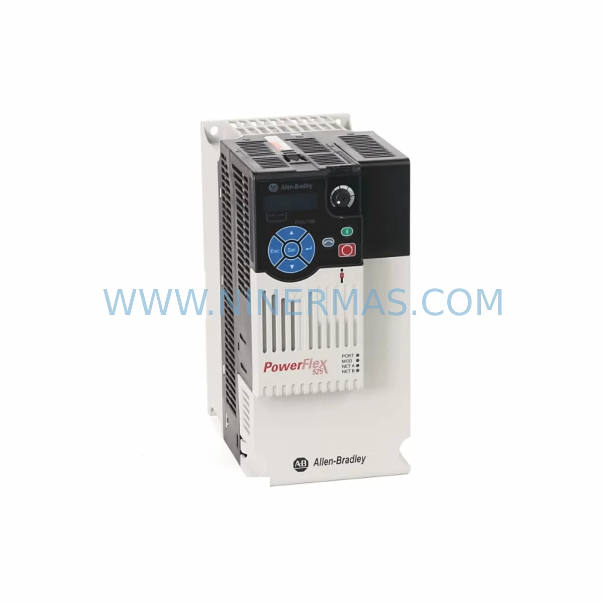
Allen-Bradley 25B-D013N104 PowerFlex 525 Retrofit Drive
Verify the part, confirm the platform family, and move straight into quotation with the right commercial details.
RFQ Ready
- SKU25B-D013N104
- CategoryPLC & Industrial Automation Modules
- BrandAllen-Bradley
- SupportAvailability, lead time, condition, and shipping coordination
How Buyers Usually Use This Page
- Confirm the exact part number and platform family before sending the quote request.
- Use direct email when quantity, condition, and destination are already defined internally.
- Switch to the broader brand or category archive when you need alternates nearby.
Series Navigation
Move through the most common platform families behind this part.
Product RFQ
Send this part directly for quotation.
Include quantity, required condition, destination country, and target delivery timing. Current reference: Allen-Bradley 25B-D013N104 PowerFlex 525 Retrofit Drive with SKU 25B-D013N104.
Allen-Bradley 25B-D013N104 PowerFlex 525 Retrofit Drive: Legacy System Compatible Upgrade
The Allen-Bradley 25B-D013N104 is a PowerFlex 525 series AC variable frequency drive rated at 240V AC, 3-phase input, 13A output current, suitable for 3HP (2.2kW) motor loads. Designed for compact panel installations, this drive is a proven retrofit solution for aging PowerFlex 4, PowerFlex 4M, and PowerFlex 40 series drives that have reached end-of-life or are no longer supported under Rockwell Automation’s standard product lifecycle. For facilities managing legacy control cabinets, the 25B-D013N104 provides a direct upgrade path with minimal rewiring and a familiar parameter structure that reduces commissioning time on the plant floor.
Upgrade Compatibility Table
| Attribute | Details |
|---|---|
| SKU / Part Number | 25B-D013N104 |
| Series | PowerFlex 525 |
| Voltage Rating | 240V AC, 3-Phase |
| Output Current | 13A |
| Motor Power | 3HP / 2.2kW |
| Communication Protocol | EtherNet/IP (embedded), DSI |
| Replaces / Upgrades From | PowerFlex 4 (22A), PowerFlex 4M (22F), PowerFlex 40 (22B) |
| Mounting | DIN rail or panel mount; Frame A/B footprint |
| Control Terminal Compatibility | Analog 0–10V / 4–20mA, Digital I/O, Relay Output |
| HMI Interface | Compatible with 25-HIM-A5 and 25-HIM-C2S LCD keypads |
| PLC Integration | ControlLogix, CompactLogix, MicroLogix via EtherNet/IP or DeviceNet adapter |
| Commissioning Tool | Connected Components Workbench (CCW), Studio 5000 Add-On Profile |
| Installation Space | Verify minimum 50mm clearance top/bottom for airflow in enclosed panels |
| Warranty | 12 Months — Pre-shipment tested, fully functional guarantee |
Retrofit Planning for Existing Automation Systems
When planning a retrofit around the 25B-D013N104, the first step is a thorough audit of the existing control cabinet. Many legacy installations still running PowerFlex 4 or PowerFlex 40 drives rely on a 22-COMM-E EtherNet/IP communication adapter or a 22-COMM-D DeviceNet adapter mounted externally. The PowerFlex 525 integrates EtherNet/IP natively, which eliminates the need for these external communication modules and simplifies the wiring harness inside the panel.
Terminal block mapping is a critical step. The 25B-D013N104 uses a standard control terminal layout with TB1 for power and TB2 for control signals. Engineers replacing a PowerFlex 40 (22B-D013N104) should verify that the analog reference signal — typically wired to terminals 1 (ACM), 2 (+10V), and 3 (AI1) — maps correctly to the 525’s equivalent terminals. Digital inputs for Run Forward, Run Reverse, and Fault Reset are generally compatible, but terminal numbering may shift by one position depending on the legacy drive revision. Always cross-reference the existing wiring diagram against the 25B-D013N104 User Manual (publication 520-UM001) before energizing.
For installations where a 1769-L33ER CompactLogix or 1756-L71 ControlLogix PLC is the host controller, the 25B-D013N104 can be added to the I/O tree using the PowerFlex 525 Add-On Profile in Studio 5000 Logix Designer. This allows the drive’s speed reference, direction command, and fault status to be mapped directly to controller tags without modifying the existing ladder logic structure — a significant advantage when downtime windows are tight. If the legacy system used a 1747-L553 SLC 5/05 or a 1747-L543 SLC 5/04 with a 1747-SDN DeviceNet Scanner, a protocol migration to EtherNet/IP may be required, and a 1783-ETAP EtherNet/IP tap or a 1783-US5T unmanaged switch should be provisioned in the panel layout.
Power supply capacity must be confirmed before installation. The 25B-D013N104 draws approximately 3.2kVA at full load. If the existing 1606-XLP power supply or a third-party 24VDC control power supply is already near capacity — particularly in panels that also power a 2711P-T10C4D8 PanelView Plus 1000 HMI, safety relays, and multiple 1734-IB8 POINT I/O modules — a power budget review is mandatory. Undersized control power is a common cause of nuisance faults during commissioning of retrofit drives.
Backplane and rack considerations apply when the drive is installed alongside a 1756 ControlLogix chassis. While the 25B-D013N104 is a standalone drive and does not occupy a rack slot, its EtherNet/IP node address must be assigned carefully to avoid conflicts with existing 1756-EN2T EtherNet/IP bridge modules, 1756-IB16 digital input modules, or 1756-OF8 analog output modules already on the network. A structured IP address scheme and a network topology diagram should be prepared before the retrofit begins.
For facilities that also need to upgrade motor branch circuit protection, the 25B-D013N104 is compatible with 140M motor protection circuit breakers and 1492-SPM supplementary protectors. If the existing installation uses a legacy 1494V disconnect switch, verify that the new drive’s input current rating aligns with the switch’s interrupting capacity. In multi-drive panels, a shared 25-RF3-AL line reactor or a 25-RF027-AL EMC filter may be required to meet conducted emissions limits, particularly in CE-marked installations.
Downtime Control During System Migration
Minimizing production downtime is the primary concern in any drive retrofit project. For the 25B-D013N104, a structured migration approach can reduce planned outage time to under four hours for a single-drive replacement in a straightforward application.
Begin by uploading and archiving the existing drive parameters using Connected Components Workbench (CCW) or a 25-HIM-A5 keypad with parameter copy function. This preserves the legacy acceleration ramp times, frequency limits, PID setpoints, and fault response configurations that the process relies on. Even if the legacy drive is a PowerFlex 40 with a different parameter numbering scheme, the functional equivalents in the PowerFlex 525 parameter set are well-documented in the migration guide (publication PFLEX-AP005).
Before removing the legacy drive, photograph all control terminal wiring and label each conductor with its terminal designation and signal function. This step alone eliminates the majority of wiring errors during reinstallation. If the panel uses a 1492-IFM20F interface module for terminal marshalling, verify that the marshalling wiring to the new drive’s TB2 control terminals is correct before applying control power.
During commissioning, use the 25B-D013N104’s built-in motor auto-tune function to characterize the connected motor. This is especially important when the motor nameplate data is unavailable or when the motor has been rewound. Auto-tune takes approximately two to five minutes and does not require the motor to be uncoupled from the load in most cases. After auto-tune, verify the output frequency, direction of rotation, and current limit settings before returning the drive to automatic control from the PLC.
If the process cannot tolerate a full stop, consider a staged migration: install the 25B-D013N104 in a temporary bypass configuration using a 25-PM1-A1 manual bypass kit or a custom contactor bypass scheme, allowing the motor to be switched between the old and new drive during the transition period. This approach is particularly effective in HVAC, pump, and conveyor applications where a brief manual speed control period is acceptable.
Post-commissioning, verify all fault and alarm conditions by simulating input signal loss, overcurrent, and communication timeout scenarios. Confirm that the PLC fault routine correctly reads the drive’s fault code via EtherNet/IP and initiates the appropriate process response. Document the final parameter set and store a backup copy in the plant’s maintenance management system alongside the updated panel wiring diagram.
Retrofit Support FAQ
Q1: Is the 25B-D013N104 a direct drop-in replacement for the PowerFlex 40 22B-D013N104?
Functionally yes — both are 240V, 13A, 3HP drives. However, the PowerFlex 525 uses a different control terminal layout and parameter numbering. A wiring diagram review and parameter remapping are required. The migration guide (PFLEX-AP005) provides a parameter cross-reference table. Physical mounting dimensions differ slightly; verify panel cutout and DIN rail spacing before installation.
Q2: What commissioning tools are needed for the 25B-D013N104?
Connected Components Workbench (CCW) v13 or later is the recommended free programming tool for standalone commissioning. For PLC-integrated installations, Studio 5000 Logix Designer with the PowerFlex 525 Add-On Profile is required. A 25-HIM-A5 or 25-HIM-C2S LCD keypad can be used for on-site parameter entry and diagnostics without a laptop.
Q3: Does the unit ship pre-tested, and what does the 12-month warranty cover?
Yes. Every 25B-D013N104 unit supplied by us undergoes pre-shipment functional testing including power-on verification, output voltage balance check, and communication port validation. The 12-month warranty covers manufacturing defects and functional failures under normal operating conditions. It does not cover damage resulting from incorrect wiring, overvoltage events, or installation in environments outside the drive’s rated IP20 enclosure specification.
Q4: What is the typical lead time and stock availability?
We maintain in-stock inventory of the 25B-D013N104 to support urgent retrofit and breakdown replacement requirements. Standard orders ship within 1–3 business days. For large-quantity project orders or scheduled maintenance programs requiring multiple units, contact us in advance to confirm allocation and lead time.
| Product Series | PowerFlex |
|---|---|
| Country of Origin | US |
Catalog Continuation
More Allen-Bradley modules in the catalog.
Use the brand lane to compare nearby part numbers, platform-adjacent modules, and other inquiry-ready listings before sending your final RFQ.
Catalog Continuation
Alternative parts within PLC & Industrial Automation Modules.
Stay inside the same system family when you need substitutes, adjacent modules, or a broader shortlist for procurement review.
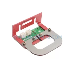
SKU: IS200EMCSG1AA
GE IS200EMCSG1AA Retrofit-Compatible Conduction Sensor Card
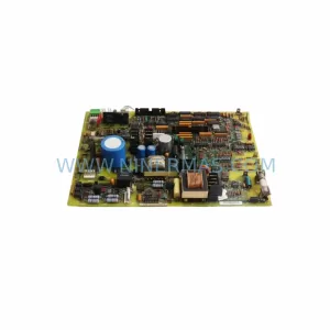
SKU: DS200IMCPG1BBA
GE DS200IMCPG1BBA Retrofit-Compatible IGBT Power Supply Board
SKU: 6ES7322-1FL00-0AA0
Siemens 6ES7322-1FL00-0AA0 Service-Ready Spare Part for Industrial Maintenance