Original Industrial Spare Part
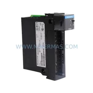
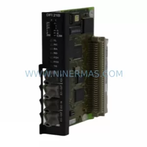
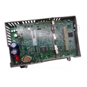
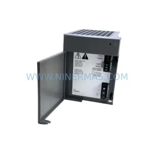
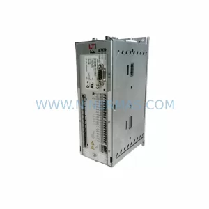
Sanyo PQM0A150EXXYST0 Retrofit-Compatible Servo Driver
Verify the part, confirm the platform family, and move straight into quotation with the right commercial details.
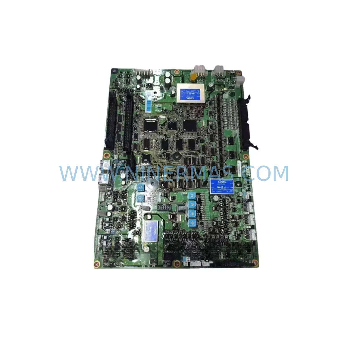
RFQ Ready
- SKUPQM0A150EXXYST0
- CategoryPLC & Industrial Automation Modules
- BrandSANYO
- SupportAvailability, lead time, condition, and shipping coordination
How Buyers Usually Use This Page
- Confirm the exact part number and platform family before sending the quote request.
- Use direct email when quantity, condition, and destination are already defined internally.
- Switch to the broader brand or category archive when you need alternates nearby.
Series Navigation
Move through the most common platform families behind this part.
Product RFQ
Send this part directly for quotation.
Include quantity, required condition, destination country, and target delivery timing. Current reference: Sanyo PQM0A150EXXYST0 Retrofit-Compatible Servo Driver with SKU PQM0A150EXXYST0.
Sanyo PQM0A150EXXYST0 Retrofit-Compatible Servo Driver: Seamless Legacy System Upgrade
The Sanyo PQM0A150EXXYST0 is a high-performance AC servo driver designed for demanding industrial automation environments. As legacy control systems age and original spare parts become increasingly scarce, the PQM0A150EXXYST0 serves as a critical retrofit solution for engineers and maintenance teams tasked with keeping production lines operational without the cost and disruption of a full system overhaul. Whether you are replacing a failed unit in a legacy Sanyo SANMOTION servo system, upgrading a multi-axis CNC control cabinet, or migrating from an obsolete servo platform, this driver delivers the electrical compatibility, form factor, and communication interface required for a smooth transition.
Procurement teams and automation engineers working with aging servo infrastructure frequently encounter the challenge of sourcing discontinued components. The PQM0A150EXXYST0 addresses this directly: it is stocked, pre-shipment tested, and backed by a 12-month warranty, giving maintenance planners the confidence to schedule replacements without emergency downtime risk. Each unit undergoes functional verification prior to dispatch, covering output current linearity, encoder feedback signal integrity, and drive enable logic — ensuring the unit arrives ready for installation.
Upgrade Compatibility Table
| Parameter | PQM0A150EXXYST0 Specification | Retrofit Notes |
|---|---|---|
| Driver Series | Sanyo SANMOTION R / P Series | Verify series compatibility with existing servo motor nameplate |
| Rated Output Current | 15A (continuous) | Confirm motor rated current does not exceed driver capacity |
| Input Voltage | 3-phase 200–230V AC, 50/60Hz | Check cabinet power supply voltage and phase configuration |
| Encoder Interface | Incremental / Absolute encoder compatible | Confirm encoder type on existing servo motor; cable pinout may differ |
| Communication Protocol | Pulse train (PULSE/DIR), Analog ±10V | Verify controller output type; MECHATROLINK-II adapter may be required for network-based systems |
| Mounting / Form Factor | Panel mount, standard DIN rail compatible | Measure cabinet depth and width; confirm cooling clearance requirements |
| Control I/O | Digital I/O: 7 inputs / 4 outputs | Remap I/O assignments in controller program if replacing a different driver model |
| Regenerative Braking | Built-in resistor; external resistor terminal available | Assess duty cycle; add external regenerative resistor for high-inertia loads |
| Replacement Compatibility | Direct replacement for PQM0A150 series variants | Cross-reference suffix codes (EXXYST0) for firmware and option card differences |
| Warranty | 12 Months | Covers manufacturing defects; pre-shipment functional test included |
Retrofit Planning for Existing Automation Systems
Integrating the PQM0A150EXXYST0 into an existing automation system requires a structured approach to avoid configuration errors and unplanned downtime. Begin by auditing the current servo drive cabinet: document the existing wiring harness, terminal block assignments, and the servo motor model connected to the outgoing unit. In many legacy installations, the servo driver shares a backplane or control rack with a Sanyo SANMOTION servo controller, a dedicated motion control card, or a third-party PLC such as a Mitsubishi MELSEC Q-series or Omron CJ-series CPU module. Understanding how the PQM0A150EXXYST0 interfaces with the upstream controller is essential before any physical swap is attempted.
Power supply capacity is the first checkpoint. The servo driver draws significant inrush current at startup; confirm that the cabinet’s 24VDC control power supply and the main 200V AC power feed can sustain the combined load of the PQM0A150EXXYST0 alongside any co-installed I/O modules, relay output modules, or signal isolators. If the existing power supply is marginal, consider upgrading to a higher-capacity unit before commissioning the new driver.
Terminal wiring is the next critical step. The PQM0A150EXXYST0 uses a standard CN1 control connector and CN2 encoder connector layout consistent with the SANMOTION P series. However, if the outgoing unit was from a different generation or a third-party equivalent, the pin assignments for servo enable (S-ON), alarm output (ALM), forward/reverse inhibit (POT/NOT), and analog speed reference may differ. Use the driver’s parameter setup software — typically Sanyo’s SANMOTION Setup Tool or a compatible RS-232C/USB programming cable — to verify and remap I/O logic before energizing the system.
For systems that previously relied on MECHATROLINK-II or other fieldbus communication, a protocol bridge or communication option card may be required. In these cases, the motion controller — whether a dedicated servo controller board, a FANUC PMC interface, or a Yaskawa MP-series motion module — must be reconfigured to recognize the new driver’s node address and axis parameters. Backup the original controller program and HMI screen data (including any GOT series or Pro-face GP panel configurations) before making any changes to the communication network topology.
Encoder cable integrity deserves special attention during retrofit. Aging shielded encoder cables can introduce noise into the feedback loop, causing position errors or drive faults even with a correctly installed new driver. Inspect the cable routing, shield grounding points, and connector condition. If the existing cable uses a 15-pin D-sub connector to a legacy absolute encoder, verify compatibility with the PQM0A150EXXYST0’s CN2 interface; an encoder cable adapter or a replacement Sanyo encoder cable assembly may be needed.
Finally, confirm that the servo motor’s mechanical brake circuit — if present — is correctly wired to the driver’s brake output terminal. In multi-axis systems sharing a common servo amplifier rack or a distributed I/O expansion chassis, ensure that the brake interlock logic in the PLC program correctly references the new driver’s alarm and ready signals before releasing the axis for automatic operation.
Downtime Control During System Migration
Minimizing production downtime during a servo driver replacement is a primary concern for plant engineers. With the PQM0A150EXXYST0, the replacement process can typically be completed within a planned maintenance window of two to four hours, provided all preparatory steps are completed in advance.
Before the maintenance window opens, prepare a complete parameter backup from the outgoing driver using the manufacturer’s setup software. Record all axis parameters: electronic gear ratio, position loop gain, velocity loop gain, acceleration/deceleration time constants, and any custom I/O logic assignments. If the outgoing driver is already non-functional and parameter backup is not possible, reconstruct the parameter set from the original commissioning documentation or from a sister machine running the same servo configuration.
During the swap, label all wiring before disconnection. Use numbered cable ties or adhesive labels on each terminal to ensure accurate reconnection. Power down the cabinet in the correct sequence — disable the servo enable signal first, then remove the main AC power, and finally disconnect the 24VDC control supply. This sequence protects both the driver and the connected servo motor from transient voltage spikes.
After physical installation of the PQM0A150EXXYST0, restore the parameter set and perform a no-load jog test before reconnecting the mechanical load. Verify that the drive’s status LEDs indicate normal operation, that the encoder feedback is correctly received (check the position display in the setup software), and that all I/O signals respond as expected. Only after confirming correct operation in manual jog mode should the axis be returned to automatic program control.
For systems with safety-critical interlocks — such as emergency stop circuits wired through a safety relay module or a dedicated safety PLC — verify that the safety chain is intact and that the new driver’s STO (Safe Torque Off) input, if applicable, is correctly connected before resuming production. Document the completed replacement in the site’s maintenance log, including the new driver’s serial number and the date of installation, to support future warranty claims and lifecycle planning.
Retrofit Support FAQ
Q1: Is the PQM0A150EXXYST0 a direct drop-in replacement for my existing Sanyo servo driver?
The PQM0A150EXXYST0 is designed as a compatible replacement within the Sanyo SANMOTION P/R series platform. In most cases it is a direct electrical and mechanical substitute for same-series units of equivalent current rating. However, suffix codes (such as EXXYST0) may indicate specific firmware versions or factory-installed option cards. Confirm the suffix against your original unit’s nameplate before ordering to ensure full compatibility.
Q2: What commissioning steps are required after installation?
After physical installation and wiring, connect a programming cable (RS-232C or USB-to-serial adapter) to the driver’s setup port and use Sanyo’s SANMOTION Setup Tool to load the backed-up parameter file. Perform a no-load jog test to verify encoder feedback, direction of rotation, and I/O signal mapping. If the system uses analog speed reference, calibrate the ±10V input scaling to match the controller’s output range. For pulse-train systems, verify the electronic gear ratio matches the original configuration before running the axis under program control.
Q3: Does the unit come with a warranty and pre-shipment testing?
Yes. Every PQM0A150EXXYST0 unit is functionally tested prior to shipment, covering output current response, encoder interface signal integrity, and drive enable/disable logic. A 12-month warranty is included from the date of shipment, covering manufacturing defects under normal operating conditions. Warranty service is coordinated directly through our sales team at sale@ninermas.com.
Q4: What is the typical lead time and stock availability?
The PQM0A150EXXYST0 is maintained in stock to support urgent replacement requirements. Standard orders are processed and dispatched within 1–3 business days. For large-quantity orders or projects requiring multiple units across a planned maintenance schedule, contact our team in advance to confirm allocation and coordinate phased delivery to match your site’s maintenance windows.
| Product Series | Other series |
|---|
Catalog Continuation
More SANYO modules in the catalog.
Use the brand lane to compare nearby part numbers, platform-adjacent modules, and other inquiry-ready listings before sending your final RFQ.
SKU: PQM1A150A5PGSSA
Sanyo PQM1A150A5PGSSA Safety-Reliable Servo for Critical Sites
SKU: PQM0A030EXXYST0 PQM0PA7R801
SANYO PQM0A030EXXYST0 PQM0PA7R801 Retrofit for PQM Series
Catalog Continuation
Alternative parts within PLC & Industrial Automation Modules.
Stay inside the same system family when you need substitutes, adjacent modules, or a broader shortlist for procurement review.