Original Industrial Spare Part
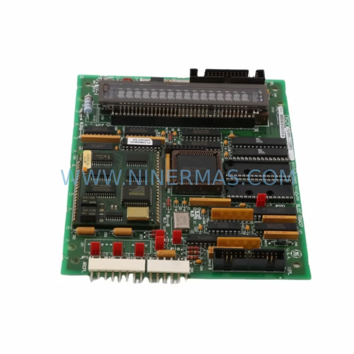
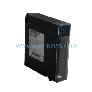
GE DS200SLCCG4AFG Retrofit-Compatible SLC for Legacy Systems
Verify the part, confirm the platform family, and move straight into quotation with the right commercial details.
RFQ Ready
- SKUDS200SLCCG4AFG
- CategoryPLC & Industrial Automation Modules
- BrandGeneral Electric
- SupportAvailability, lead time, condition, and shipping coordination
How Buyers Usually Use This Page
- Confirm the exact part number and platform family before sending the quote request.
- Use direct email when quantity, condition, and destination are already defined internally.
- Switch to the broader brand or category archive when you need alternates nearby.
Series Navigation
Move through the most common platform families behind this part.
Product RFQ
Send this part directly for quotation.
Include quantity, required condition, destination country, and target delivery timing. Current reference: GE DS200SLCCG4AFG Retrofit-Compatible SLC for Legacy Systems with SKU DS200SLCCG4AFG.
GE DS200SLCCG4AFG Retrofit-Compatible SLC for Legacy Systems
The GE DS200SLCCG4AFG is a Slave Link Controller (SLC) board engineered for the GE DS200 Drive Series — one of the most widely deployed digital drive platforms in heavy industrial environments including power generation, oil & gas, steel mills, and water treatment facilities. As original OEM supply chains for the DS200 series have tightened and many sub-assemblies have reached end-of-life status, the DS200SLCCG4AFG has become a critical retrofit and replacement component for engineers tasked with extending the operational life of legacy drive systems without undertaking a full platform migration.
This board serves as the communication and control backbone within the DS200 drive cabinet, managing slave link communications between the main controller and peripheral I/O modules. In retrofit scenarios, the DS200SLCCG4AFG is typically replaced when engineers observe intermittent communication faults, loss of feedback signals, or drive trip events that cannot be resolved through parameter adjustment or cable reseating. Before sourcing a replacement, technicians should verify the board revision level against the existing backplane connector layout, as minor hardware revisions within the DS200 family — such as those found on the DS200SDCCG3A (Signal Distribution Control Card) — can affect pin compatibility and firmware handshake behavior.
Upgrade Compatibility Table
| Parameter | Details |
|---|---|
| SKU / Part Number | DS200SLCCG4AFG |
| Series | GE DS200 Drive Series |
| Board Function | Slave Link Controller (SLC) — inter-board communication management |
| Backplane Interface | DS200 standard backplane; verify connector row count before installation |
| Communication Compatibility | Slave Link protocol; compatible with DS200 series master controllers |
| Installation Requirement | Match board slot position per original drive documentation; confirm rack orientation |
| Replacement Recommendation | Direct replacement for DS200SLCCG4AFG; cross-check revision suffix (G4AFG) with site records |
| Commissioning Focus | Re-establish slave link addresses; verify I/O feedback signals; clear fault history before restart |
| Interface Differences vs. Older Revisions | G4 revision may include updated EPROM; confirm firmware version compatibility with host controller |
| Warranty | 12-Month Warranty — covers manufacturing defects and functional failure under normal operating conditions |
Retrofit Planning for Existing Automation Systems
Successful integration of the DS200SLCCG4AFG into an existing drive cabinet begins well before the board is physically installed. Retrofit planning for DS200-based systems requires a structured review of the entire control architecture. Engineers should start by auditing the DS200 backplane for physical damage, oxidized contacts, or cracked PCB traces — issues that are common in systems that have operated for 15 or more years in high-vibration or high-humidity environments. A damaged backplane will cause recurring faults even after a new SLC board is installed.
Power supply integrity is the next critical checkpoint. The DS200PCCAG1A (Power Supply Board) within the DS200 rack must deliver stable regulated voltages to all board slots. Voltage sag or ripple on the 5V or 15V rails will cause the DS200SLCCG4AFG to generate spurious communication errors that mimic board failure. Use a calibrated oscilloscope to verify rail stability under load before condemning the SLC board.
Terminal wiring adaptation is frequently required when the DS200SLCCG4AFG is installed as part of a broader control cabinet upgrade. If the site is migrating from an older relay-logic panel to a DS200-based drive system, field wiring terminations must be re-mapped to match the I/O assignments expected by the DS200IOCAG1A (I/O Controller Board). Document all existing field wiring before disconnection, and use terminal block labeling to preserve traceability during the rewiring process.
For sites that are also upgrading their HMI layer, the DS200SLCCG4AFG retrofit often coincides with replacement of legacy operator panels. Engineers migrating to modern SCADA or HMI platforms should verify that the communication protocol exported by the DS200 master controller — typically via a DS200CPCAG1A (Communication Processor Card) — is compatible with the new HMI’s driver library. Protocol mismatches between the drive and the HMI are a common source of commissioning delays that extend planned downtime windows.
I/O expansion requirements should also be assessed during the retrofit planning phase. If the upgraded system requires additional analog or digital I/O points beyond what the existing DS200DSPAG1A (Digital Signal Processor Board) configuration supports, additional I/O modules must be sourced and rack space must be confirmed before the outage window begins. Attempting to add I/O modules during an active retrofit without pre-planning rack slot availability is a leading cause of schedule overruns.
Signal isolation is another consideration for legacy line retrofits. Where the DS200 system interfaces with older 4–20mA transmitters or thermocouple inputs from legacy instrumentation, signal isolators should be installed between field devices and the DS200 I/O terminals to prevent ground loop interference. This is particularly important in steel mill and power plant environments where ground potential differences between control cabinets can be significant.
Programming cable access should be confirmed prior to the outage. The DS200 programming interface requires a compatible serial or USB-to-serial adapter for parameter upload and download. Technicians should pre-load the existing parameter set from site records or perform a parameter backup via the DS200 HMI terminal before the SLC board is removed, ensuring that drive configuration is not lost during the board swap.
Downtime Control During System Migration
Minimizing unplanned downtime during a DS200SLCCG4AFG replacement requires a disciplined pre-outage preparation protocol. The most effective approach is to treat the board replacement as a planned maintenance event with a defined time budget — typically 4 to 8 hours for an experienced drive technician performing a single-board swap with parameter verification.
Before the outage begins, the site team should complete the following preparatory steps: confirm that the replacement DS200SLCCG4AFG has been bench-tested and verified functional; retrieve and print the existing drive parameter list from the site’s maintenance management system; photograph all existing board positions, cable routing, and terminal connections within the drive cabinet; and confirm that all necessary tools, including torque drivers, ESD wrist straps, and a laptop with the appropriate drive configuration software, are staged at the work location.
During the outage, the sequence of operations should follow a strict board-out, board-in, power-up, and verify protocol. After the new DS200SLCCG4AFG is seated and secured, power should be applied incrementally — first to the control power circuit, then to the main drive bus — while monitoring for fault codes on the drive’s status display. Slave link communication should be verified by confirming that all downstream I/O boards, including any DS200TBQCG1A (Terminal Board) assemblies, are recognized by the master controller before the drive is released for production restart.
Original program logic should never be modified during a board replacement outage unless a specific fault condition requires parameter adjustment. Changes to drive parameters during an unplanned outage introduce risk of misconfiguration that can cause equipment damage or personnel safety events. If parameter changes are required, they should be documented, reviewed by a qualified engineer, and tested under no-load conditions before the drive is returned to service.
Post-replacement, a 30-minute supervised run at reduced load is recommended to confirm stable operation before full production load is applied. This run period allows the DS200SLCCG4AFG to establish stable thermal equilibrium and confirms that all slave link communications remain error-free under operating conditions.
Retrofit Support FAQ
Q1: Is the DS200SLCCG4AFG a direct drop-in replacement for earlier DS200 SLC board revisions?
In most cases, yes — the DS200SLCCG4AFG (G4AFG revision) is designed to be backward compatible with earlier DS200 SLC board revisions within the same drive family. However, engineers should verify the EPROM or firmware version installed on the replacement board against the host controller’s expected firmware handshake. In rare cases, a firmware update to the master controller board may be required to achieve full compatibility. Our technical team can assist with revision cross-referencing prior to shipment.
Q2: What pre-shipment testing is performed on the DS200SLCCG4AFG before delivery?
Each DS200SLCCG4AFG unit supplied by NINERMAS undergoes functional verification testing prior to shipment. Testing includes power-on self-test confirmation, communication link verification, and visual inspection for component-level defects. Units are shipped in ESD-protective packaging with individual test records available upon request. All units are covered by a 12-Month Warranty against manufacturing defects and functional failure under normal operating conditions.
Q3: How do I confirm correct terminal wiring when installing the DS200SLCCG4AFG in a retrofitted cabinet?
Terminal wiring for the DS200SLCCG4AFG should be referenced against the original GE DS200 drive wiring diagram for your specific drive model and cabinet configuration. If original documentation is unavailable, NINERMAS can provide general wiring guidance based on the drive series and application type. It is strongly recommended to photograph all existing wiring before removal and to use a continuity tester to verify each connection after rewiring is complete. Do not rely on wire color coding alone, as field modifications over the life of the system may have altered original color conventions.
Q4: What is the typical lead time and stock availability for the DS200SLCCG4AFG?
NINERMAS maintains inventory of the DS200SLCCG4AFG to support urgent retrofit and emergency replacement requirements. Standard orders are processed and shipped within 1–3 business days. For time-critical plant outage situations, expedited processing is available — contact our sales team directly to confirm current stock levels and arrange priority dispatch. All units are supplied with a 12-Month Warranty and full traceability documentation.
| Product Series | Mark V |
|---|---|
| Country of Origin | US |
Catalog Continuation
More General Electric modules in the catalog.
Use the brand lane to compare nearby part numbers, platform-adjacent modules, and other inquiry-ready listings before sending your final RFQ.
Catalog Continuation
Alternative parts within PLC & Industrial Automation Modules.
Stay inside the same system family when you need substitutes, adjacent modules, or a broader shortlist for procurement review.