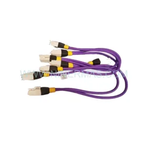
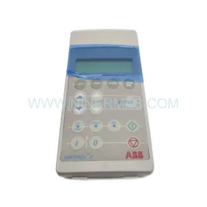
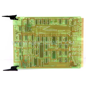
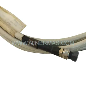
Original Industrial Spare Part
LASER TLS-18-21-82-01-V02 Retrofit-Compatible Control Unit
Verify the part, confirm the platform family, and move straight into quotation with the right commercial details.
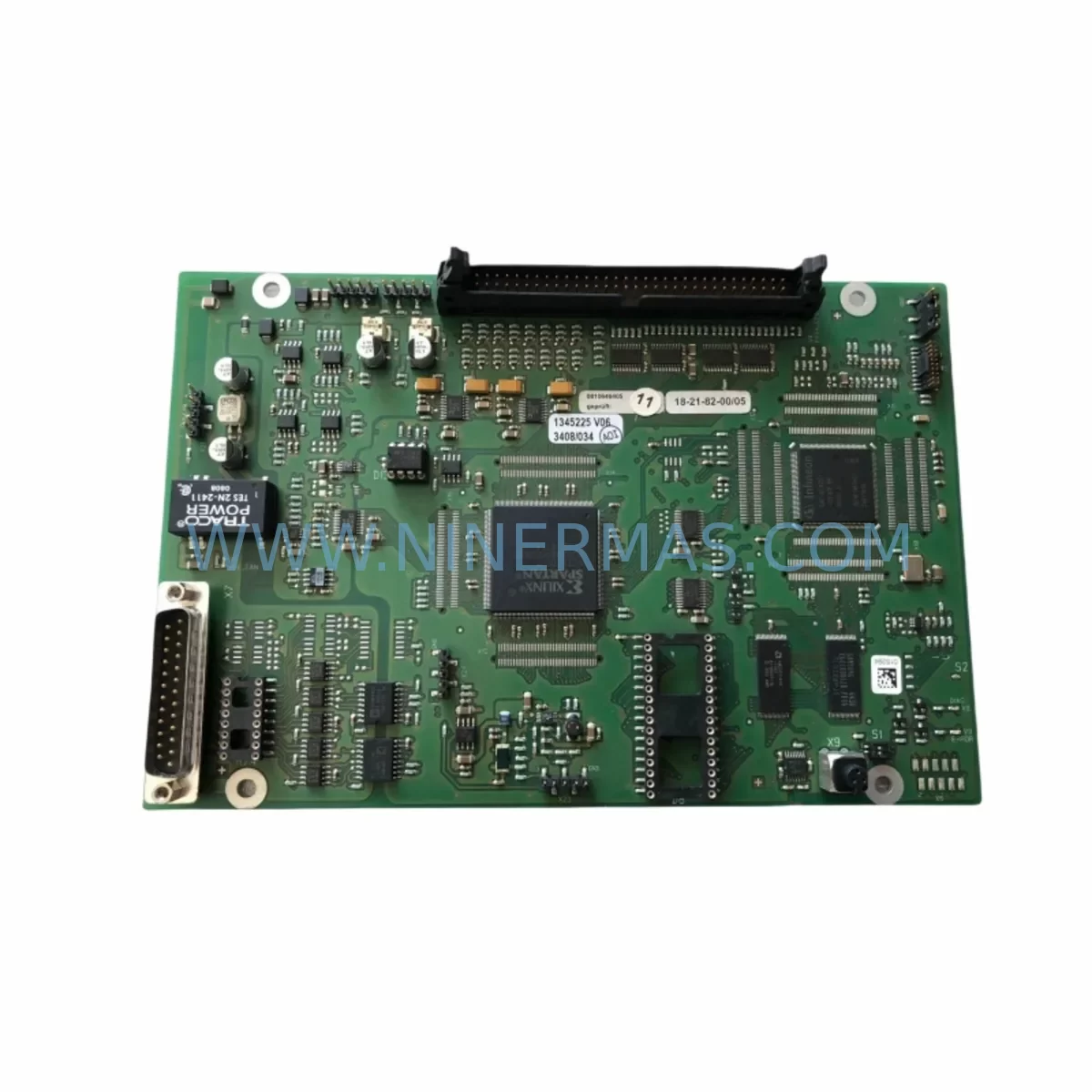
RFQ Ready
- SKU18-21-82-00/05 TLS-18-21-82-01-V02
- CategorySIS Safety & Redundancy Systems
- BrandLASER
- SupportAvailability, lead time, condition, and shipping coordination
How Buyers Usually Use This Page
- Confirm the exact part number and platform family before sending the quote request.
- Use direct email when quantity, condition, and destination are already defined internally.
- Switch to the broader brand or category archive when you need alternates nearby.
Series Navigation
Move through the most common platform families behind this part.
Product RFQ
Send this part directly for quotation.
Include quantity, required condition, destination country, and target delivery timing. Current reference: LASER TLS-18-21-82-01-V02 Retrofit-Compatible Control Unit with SKU 18-21-82-00/05 TLS-18-21-82-01-V02.
LASER TLS-18-21-82-01-V02 Retrofit-Compatible Control Unit for Legacy System Modernization
The LASER 18-21-82-00/05 TLS-18-21-82-01-V02 is a retrofit-compatible safety control unit engineered for seamless integration into aging industrial automation infrastructures. As legacy control architectures approach end-of-life, plant engineers and maintenance teams face mounting pressure to source reliable replacement modules that preserve existing wiring topologies, maintain program logic continuity, and minimize unplanned downtime. This unit addresses those challenges directly, offering a verified drop-in replacement path for facilities operating LASER TLS-18 series safety relay platforms.
Whether your facility is managing a phased modernization of a legacy control cabinet, replacing a discontinued safety module in a production line, or executing an emergency spare-parts substitution to restore operations, the TLS-18-21-82-01-V02 delivers the electrical and mechanical compatibility required to complete the retrofit with confidence. Its terminal layout, backplane interface geometry, and signal logic architecture align with the original TLS-18 series specification, reducing re-engineering effort and accelerating return-to-service timelines.
Before committing to installation, engineers should verify several critical parameters. Power supply capacity must be confirmed against the control cabinet’s 24 VDC bus loading — particularly where multiple safety relay modules share a common LASER PSU-24 or equivalent power distribution rail. Terminal wiring compatibility should be cross-referenced against the original wiring diagram, paying close attention to the dual-channel input configuration, feedback loop terminals, and output relay contact ratings. If the existing cabinet uses a LASER TLS-18 backplane or DIN-rail mounting assembly, the module’s physical footprint and connector pitch must be verified to ensure zero-modification installation.
For facilities running integrated safety architectures, the TLS-18-21-82-01-V02 is commonly deployed alongside the LASER TLS-18-21-82-00 base module and TLS-18-21-82-02 expansion relay, forming a coordinated safety chain across E-stop circuits, light curtain interfaces, and two-hand control stations. In cabinet configurations where the safety relay communicates upstream to a PLC — such as a SIEMENS S7-300 or ALLEN-BRADLEY MicroLogix — the output relay contacts must be mapped correctly to the PLC’s digital input card, and the program logic verified to confirm that the safety function response time remains within the original SIL or PLd certification envelope.
Facilities upgrading from older LASER safety relay generations should also assess module address configuration if the safety system uses a networked architecture with PROFIBUS DP or AS-Interface communication. In such cases, the replacement module’s node address must be set to match the original before power-up to prevent communication faults on the safety bus. Where the original module used a rotary address switch, the TLS-18-21-82-01-V02’s addressing method should be confirmed against the system’s network topology documentation.
HMI screen updates are frequently overlooked during safety relay replacements. If the control system includes a SIEMENS TP700 Comfort, WEINTEK MT8000, or equivalent operator panel with alarm pages referencing the original module’s diagnostic outputs, those screen objects should be reviewed and updated to reflect the replacement module’s fault code structure. Failure to align HMI alarm logic with the new module can result in misleading fault indications during commissioning.
Installation space confirmation is essential in densely populated control cabinets. The TLS-18-21-82-01-V02 occupies a standard 22.5 mm DIN-rail slot width, consistent with the TLS-18 series form factor. Engineers should verify available rail space and confirm that adjacent modules — including terminal blocks, I/O expansion cards, and communication gateways — do not obstruct the module’s ventilation clearance or wiring access.
Post-installation commissioning should follow a structured validation sequence: power-on self-test confirmation, input channel functional test using the original actuator (E-stop button, safety gate switch, or light curtain), output relay contact verification using a calibrated continuity tester, and a full safety function cycle test with the machine in a controlled state. Where the original system was certified to ISO 13849-1 PLd or IEC 62061 SIL 2, the replacement module’s datasheet should be reviewed to confirm equivalent performance parameters before the system is returned to production.
Upgrade Compatibility Table
| Parameter | Original / Legacy | TLS-18-21-82-01-V02 (Replacement) |
|---|---|---|
| Supply Voltage | 24 VDC | 24 VDC (±20%) |
| Mounting Interface | DIN Rail / TLS-18 Backplane | DIN Rail / TLS-18 Backplane (direct fit) |
| Terminal Wiring | Screw terminal, dual-channel input | Screw terminal, dual-channel input (compatible) |
| Communication | Hardwired / AS-Interface (optional) | Hardwired / AS-Interface (compatible) |
| Output Relay Contacts | 2 NO safety contacts | 2 NO safety contacts (equivalent rating) |
| Safety Rating | SIL 2 / PLd (ISO 13849-1) | SIL 2 / PLd (verified equivalent) |
| Installation Width | 22.5 mm DIN slot | 22.5 mm DIN slot (no modification required) |
| Retrofit Recommendation | — | Direct replacement; verify wiring and address |
| Commissioning Focus | — | Input channel test, output relay verification, safety cycle test |
| Warranty | — | 12-Month Warranty (NINERMAS) |
Retrofit Planning for Existing Automation Systems
A successful retrofit begins well before the replacement module arrives on site. Maintenance planners should compile the original cabinet documentation — including wiring schematics, PLC I/O assignment tables, and the safety relay’s original commissioning report — and cross-reference these against the TLS-18-21-82-01-V02 datasheet. In multi-zone safety architectures, where the TLS-18 series module interfaces with a LASER TLS-18-21-82-00 base unit and one or more TLS-18-21-82-02 expansion relays, the replacement sequence must be planned to maintain safety chain continuity across all zones during the transition.
Power distribution planning is critical. Where the control cabinet uses a LASER PSU-24/10 power supply module or equivalent 24 VDC rail, the additional current draw of the replacement module should be calculated against the available headroom. In cabinets where I/O density is high — incorporating PHOENIX CONTACT QUINT or WAGO 787 series power supplies alongside the safety relay — load balancing across the 24 VDC bus must be verified before energizing the replacement module.
For systems integrating PILZ PNOZ or SCHMERSAL SRB series safety relays in adjacent zones, the TLS-18-21-82-01-V02’s output contact timing and reset behavior should be confirmed to be compatible with the cross-monitoring logic of those adjacent devices. Signal isolation may be required where the safety relay’s output feeds into a PHOENIX CONTACT MCR-SL signal isolator or equivalent galvanic isolation barrier before reaching the PLC input card.
Communication link integrity must be preserved throughout the retrofit. In systems where the safety relay’s diagnostic output connects to a SIEMENS ET 200SP distributed I/O station or a BECKHOFF EK1100 EtherCAT coupler, the fieldbus segment must remain operational during module swap to prevent cascading faults on the network. Where a programming cable — such as a LASER USB-to-serial adapter or equivalent — is required for parameter configuration, this should be prepared and tested before the maintenance window begins.
Physical installation should be executed with the cabinet de-energized and locked out per LOTO procedures. After seating the TLS-18-21-82-01-V02 on the DIN rail and reconnecting all terminal wiring, a pre-power-up insulation resistance check is recommended to confirm wiring integrity before energizing the 24 VDC supply.
Downtime Control During System Migration
Minimizing production downtime during a safety relay replacement requires a disciplined pre-outage preparation strategy. All replacement components — including the TLS-18-21-82-01-V02 module, spare terminal ferrules, and any required DIN rail hardware — should be staged and verified before the maintenance window opens. A pre-tested spare module, confirmed functional on a bench test rig using a LASER TLS-18 test harness or equivalent, eliminates the risk of discovering a defective replacement unit after the production line has been taken offline.
Original program logic should be backed up from the PLC — whether a SIEMENS S7-1200, OMRON CJ2M, or MITSUBISHI FX5U — before any hardware changes are made. Safety function parameters, if stored in the relay module itself, should be documented and, where possible, exported using the manufacturer’s configuration tool. This ensures that if the replacement module requires parameter re-entry, the correct values are available without relying on memory or incomplete documentation.
During the swap, maintaining field control continuity may be possible by temporarily bypassing non-critical safety zones under a formal risk assessment and permit-to-work, allowing adjacent production cells to remain operational while the affected zone is isolated. Once the TLS-18-21-82-01-V02 is installed and wired, a structured recommissioning sequence — power-on self-test, input channel functional test, output relay contact verification, and a witnessed safety function cycle test — should be completed before the zone is returned to automatic operation.
Post-commissioning, a 24-hour monitored run period is recommended to confirm stable operation under normal production load conditions. Any diagnostic LEDs or fault outputs from the replacement module should be monitored during this period to detect latent wiring issues or parameter mismatches before they escalate to unplanned stoppages.
Retrofit Support FAQ
Q1: Is the LASER TLS-18-21-82-01-V02 a direct replacement for the original 18-21-82-00/05 module?
Yes. The TLS-18-21-82-01-V02 is designed as a retrofit-compatible replacement for the 18-21-82-00/05 within the LASER TLS-18 series platform. Terminal wiring, DIN rail mounting, and backplane interface geometry are consistent with the original specification. Engineers should verify the dual-channel input wiring and output relay contact assignments against the original wiring diagram before installation.
Q2: What commissioning steps are required after installation?
After physical installation and terminal reconnection, perform a power-on self-test to confirm the module initializes without fault. Execute a functional test of each input channel using the original actuator (E-stop, safety gate, or light curtain). Verify output relay contact continuity using a calibrated tester, then complete a full safety function cycle test with the machine in a controlled state. Document all test results before returning the system to production.
Q3: Does NINERMAS provide pre-shipment testing for this module?
Yes. All LASER TLS-18-21-82-01-V02 units supplied by NINERMAS undergo pre-shipment functional verification to confirm power-on initialization, input channel response, and output relay operation. Units are shipped with a test confirmation record. A 12-month warranty is provided from the date of shipment, covering manufacturing defects and functional failures under normal operating conditions.
Q4: What is the typical lead time and stock availability?
NINERMAS maintains stock of the LASER TLS-18-21-82-01-V02 to support emergency replacement and planned maintenance schedules. Standard orders are processed within 1–2 business days. For urgent requirements, expedited dispatch is available — contact our team directly to confirm current stock levels and shipping options for your region.
| Product Series | Other series |
|---|
Catalog Continuation
More LASER modules in the catalog.
Use the brand lane to compare nearby part numbers, platform-adjacent modules, and other inquiry-ready listings before sending your final RFQ.
Catalog Continuation
Alternative parts within SIS Safety & Redundancy Systems.
Stay inside the same system family when you need substitutes, adjacent modules, or a broader shortlist for procurement review.
SKU: 51303940-250 ,51303940-150
Honeywell 51303940-250 Safety-Reliable PSU for Critical Sites
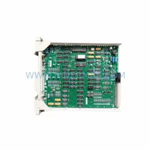
SKU: 51304487-100 MU-PDOX02
Honeywell 51304487-100 MU-PDOX02 Safety-Reliable Digital Output Module
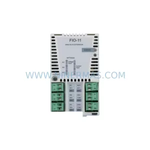
SKU: FIO-11 68679079
ABB FIO-11 68679079 Safety-Reliable Analogue I/O Module