Original Industrial Spare Part
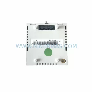
KUKA 00-207-218 GA12 Retrofit Drive for Legacy Systems
Verify the part, confirm the platform family, and move straight into quotation with the right commercial details.
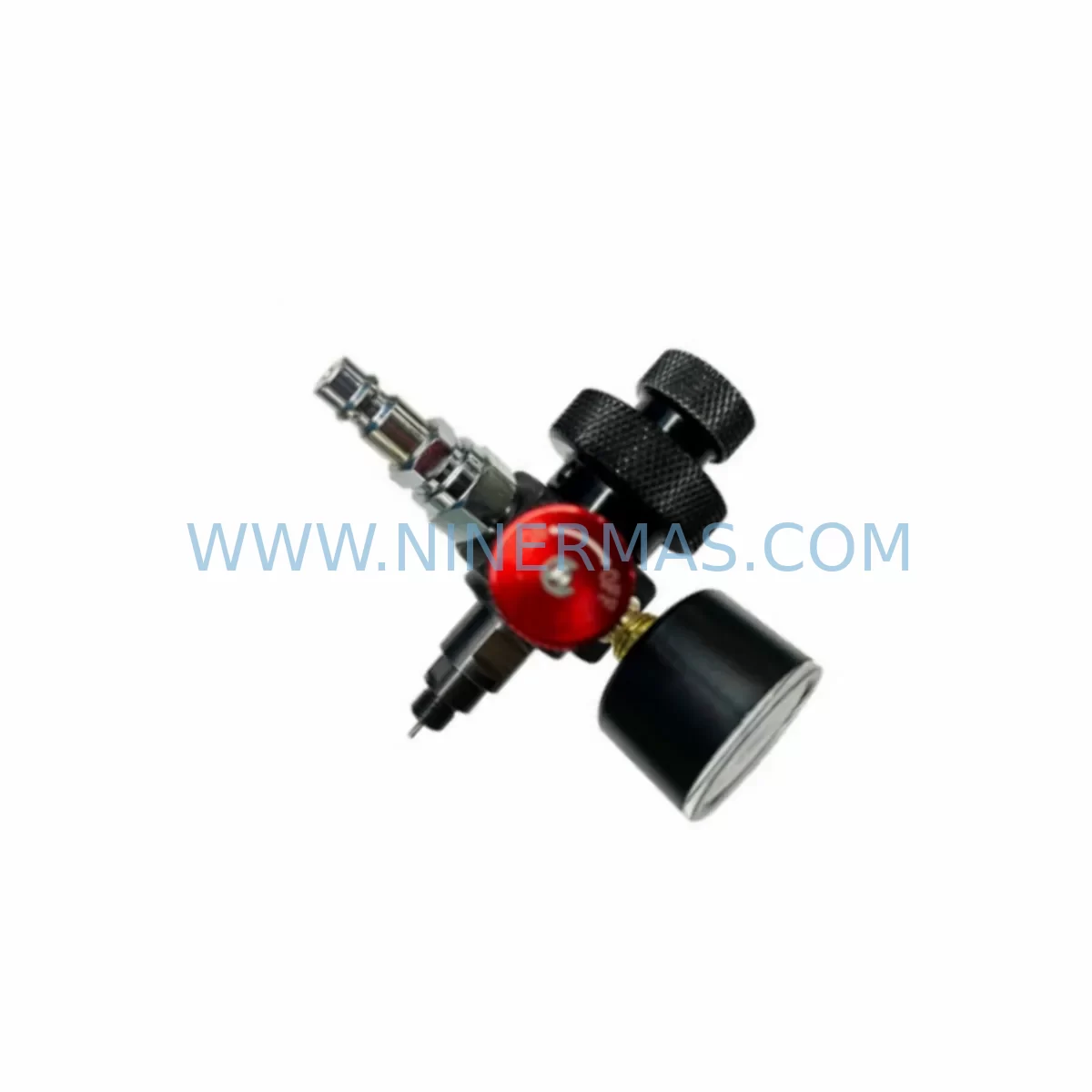
RFQ Ready
- SKU00-207-218 C4 GA12
- CategoryPLC & Industrial Automation Modules
- BrandKUKA
- SupportAvailability, lead time, condition, and shipping coordination
How Buyers Usually Use This Page
- Confirm the exact part number and platform family before sending the quote request.
- Use direct email when quantity, condition, and destination are already defined internally.
- Switch to the broader brand or category archive when you need alternates nearby.
Series Navigation
Move through the most common platform families behind this part.
Product RFQ
Send this part directly for quotation.
Include quantity, required condition, destination country, and target delivery timing. Current reference: KUKA 00-207-218 GA12 Retrofit Drive for Legacy Systems with SKU 00-207-218 C4 GA12.
KUKA 00-207-218 GA12 Retrofit Drive for Legacy Systems
The KUKA 00-207-218 C4 GA12 is a retrofit-compatible drive module engineered for the KR C4 robot controller platform — one of KUKA’s most widely deployed industrial robot control architectures across automotive, metal fabrication, and general manufacturing environments. As production lines age and original spare parts enter end-of-life status, the 00-207-218 C4 GA12 provides a verified replacement path that preserves existing wiring infrastructure, backplane addressing, and axis program logic without requiring a full controller overhaul.
Facilities operating legacy KUKA KR C4 cabinets frequently encounter the challenge of sourcing discontinued axis drive components. The 00-207-218 module addresses this directly: it is dimensionally compatible with the KR C4 controller cabinet’s standard drive slot, maintains the same terminal block pinout as the original unit, and supports the KR C4’s internal EtherCAT communication bus — eliminating the need for protocol migration or PLC reprogramming during the swap procedure.
When planning a retrofit around this drive module, engineers should confirm the cabinet’s 24 VDC logic supply capacity and the DC link bus voltage delivered by the KR C4 power supply unit (PSU). The GA12 designation indicates compatibility with KUKA’s GA-series axis grouping, which typically governs axes 1–3 or 4–6 depending on robot model configuration. Verify the axis assignment in the robot’s KUKA System Software (KSS) configuration file before removal of the original module to avoid axis address conflicts during recommissioning.
Upgrade Compatibility Table
| Parameter | Original Unit | 00-207-218 C4 GA12 | Retrofit Notes |
|---|---|---|---|
| Platform | KUKA KR C4 | KUKA KR C4 | Direct platform match — no controller change required |
| Communication Bus | EtherCAT (internal) | EtherCAT (internal) | No protocol migration needed |
| Axis Group | GA12 (axes per KSS config) | GA12 | Confirm axis address in KSS before swap |
| Terminal Wiring | Standard KR C4 terminal block | Compatible terminal block | Label and photograph all wiring before disconnection |
| Backplane Interface | KR C4 drive slot connector | KR C4 drive slot connector | Seat firmly; verify connector lock engagement |
| Installation Space | Standard KR C4 drive bay | Same form factor | No cabinet modification required |
| Program Compatibility | KSS / KUKA.WorkVisual | KSS / KUKA.WorkVisual | Existing robot programs remain valid post-swap |
| HMI / SmartPAD | KUKA SmartPAD | Compatible | No HMI screen reconfiguration required |
| Pre-Shipment Test | — | Full functional test | Tested before dispatch from NINERMAS |
| Warranty | — | 12-Month Warranty | Covered from date of delivery |
Retrofit Planning for Existing Automation Systems
A successful retrofit of the KUKA 00-207-218 C4 GA12 into an existing production line requires a structured pre-installation audit. Begin by documenting the full KR C4 cabinet configuration: record the positions of all installed drive modules, the KR C4 power supply unit (PSU) output ratings, and the current firmware version running on the KUKA Controller Board (CCU). This baseline ensures that the replacement drive module is introduced into a known-good electrical environment.
Terminal wiring is a critical checkpoint. The KR C4 cabinet uses a structured terminal block layout that connects motor power cables, resolver feedback lines, and brake control signals for each axis group. Before removing the original GA12 drive, photograph and label every connector. Cross-reference against the robot’s wiring diagram — available in KUKA.WorkVisual — to confirm that the motor power connector (X20/X30 series) and the resolver cable are correctly re-seated on the replacement module.
For facilities running multiple KUKA robots on a shared network, the KUKA KR C4 Ethernet KRL interface or PROFINET adapter module may be present in the cabinet. These communication modules are independent of the axis drive and do not require reconfiguration during a drive swap — however, confirming that the EtherCAT ring topology remains intact after module replacement is essential before powering up. A broken EtherCAT ring will prevent the controller from initializing any axis.
I/O expansion cards installed in the KR C4 — such as the KUKA KR C4 I/O module or third-party Beckhoff EtherCAT I/O terminals integrated into the cabinet — should be verified for address conflicts after the drive replacement. The KSS axis configuration assigns each GA-series drive a unique node address on the internal bus; if the replacement module ships with a default address, it must be set to match the original before the first power-on.
HMI continuity is another consideration. Facilities using the KUKA SmartPAD or an external KUKA OfficeLite simulation environment for program validation should confirm that the teach pendant remains responsive after the swap. In most cases, the SmartPAD requires no reconfiguration — but if the cabinet was running a customized KSS version with axis-specific safety parameters, those parameters should be re-validated using the KUKA.SafeOperation package before returning the robot to automatic mode.
Where the retrofit involves older KR C4 cabinets originally paired with KUKA KR 6, KR 16, or KR 30 robot arms, the GA12 drive’s current rating should be cross-checked against the motor nameplate data for the specific arm model. NINERMAS provides pre-shipment compatibility verification for all 00-207-218 C4 GA12 units against the customer’s declared robot model and serial number range, reducing the risk of a mismatch before the unit arrives on site.
For multi-robot cells undergoing phased upgrades, the 00-207-218 module can be staged as a hot-spare alongside existing operational drives. This approach — combined with a pre-tested unit from NINERMAS stock — allows maintenance teams to execute the physical swap during a planned micro-shutdown window of 2–4 hours rather than an extended production halt.
Downtime Control During System Migration
Minimizing unplanned downtime is the primary operational concern when replacing a drive module in an active production environment. The KUKA 00-207-218 C4 GA12 retrofit process is designed to support a controlled, low-risk swap procedure that protects existing program logic and maintains field control continuity throughout the migration.
The recommended approach begins with a full KSS project backup using KUKA.WorkVisual before any hardware is touched. This backup captures the complete robot configuration — axis parameters, safety zones, I/O mappings, and program files — and can be restored to the replacement drive within minutes if any configuration discrepancy is detected during commissioning. Store the backup on both the controller’s internal memory and an external USB device.
During the physical swap, the KR C4 cabinet should be placed in E-Stop with main power isolated at the cabinet disconnect. Allow the DC link bus to discharge fully (typically 5 minutes after power-off) before opening the drive bay. This protects both the technician and the replacement module from residual voltage damage. The 00-207-218 module’s backplane connector should be seated with firm, even pressure — a partially engaged connector is the most common cause of post-swap EtherCAT communication faults.
After physical installation, power the cabinet in T1 (manual reduced speed) mode and perform a full axis mastering check using the KUKA SmartPAD. Confirm that all axes respond correctly to jog commands before advancing to T2 or Automatic mode. If the robot was previously mastered with an Electronic Mastering Device (EMD), re-mastering may be required after the drive swap — plan for this step in the shutdown window to avoid delays.
For facilities with strict OEE targets, NINERMAS recommends maintaining at least one pre-tested 00-207-218 C4 GA12 unit in local inventory as a cold-spare. With a tested spare on hand, the total swap-and-recommission cycle can be completed within a single shift, keeping unplanned downtime within acceptable limits and avoiding the lead-time risk associated with emergency procurement of discontinued components.
Retrofit Support FAQ
Q1: Is the KUKA 00-207-218 C4 GA12 a direct replacement for the original drive module in my KR C4 cabinet?
Yes. The 00-207-218 C4 GA12 is dimensionally and electrically compatible with the original drive slot in the KUKA KR C4 controller cabinet. It uses the same backplane connector, terminal block layout, and EtherCAT communication interface as the original unit. No cabinet modification or protocol reconfiguration is required for a standard swap.
Q2: Will my existing robot programs and KSS configuration remain valid after the replacement?
In the vast majority of cases, yes. The 00-207-218 module operates within the same KSS software environment as the original drive. Existing axis parameters, safety configurations, and robot programs are stored on the KR C4 controller board (CCU) — not on the drive module itself — and are preserved through the swap. A full KSS project backup via KUKA.WorkVisual is still strongly recommended before any hardware change.
Q3: What pre-shipment testing does NINERMAS perform on the 00-207-218 C4 GA12?
Every unit dispatched by NINERMAS undergoes a full functional test prior to shipment, including power-on verification, communication bus integrity check, and output signal validation. Units are inspected for physical condition and packed in anti-static, shock-protected packaging. A test report is available upon request. All units are covered by a 12-month warranty from the date of delivery.
Q4: What is the typical lead time, and does NINERMAS maintain stock of the 00-207-218 C4 GA12?
NINERMAS maintains in-stock inventory of the KUKA 00-207-218 C4 GA12 to support urgent replacement requirements. Standard lead time for in-stock units is 3–7 business days for international shipments, depending on destination. For time-critical situations, expedited dispatch options are available. Contact our team at sale@ninermas.com or +0086 187 5021 5667 to confirm current stock availability and lead time for your location.
| Product Series | Legacy |
|---|---|
| Country of Origin | DE |
Catalog Continuation
More KUKA modules in the catalog.
Use the brand lane to compare nearby part numbers, platform-adjacent modules, and other inquiry-ready listings before sending your final RFQ.
SKU: KPP 600-20 2X40 :00-160-152 KPP 600-20 3X20 UL :00-245-213 KPP 600-20 UL :00-198-259
KUKA KPP-600-20 Retrofit Power Supply for Legacy Systems
SKU: 00-106-446kr150.kr180 ZH150/180
KUKA 00-106-446 Retrofit-Compatible Gearbox for Legacy Systems
Catalog Continuation
Alternative parts within PLC & Industrial Automation Modules.
Stay inside the same system family when you need substitutes, adjacent modules, or a broader shortlist for procurement review.
SKU: TRY/PRG/4-20MA/10-30DC
MOORE TRY/PRG/4-20MA/10-30DC Service-Ready Spare Part
SKU: 5085-404901-11 12INCH 2910-202413-12 404200XRMPD2H14 7-249717
TEL 5085-404901-11 Service-Ready Spare Part for Industrial Maintenance
SKU: DIP011 05-058-011
SIGMATEK DIP011 05-058-011 Service-Ready Spare Part