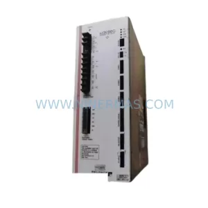
Original Industrial Spare Part
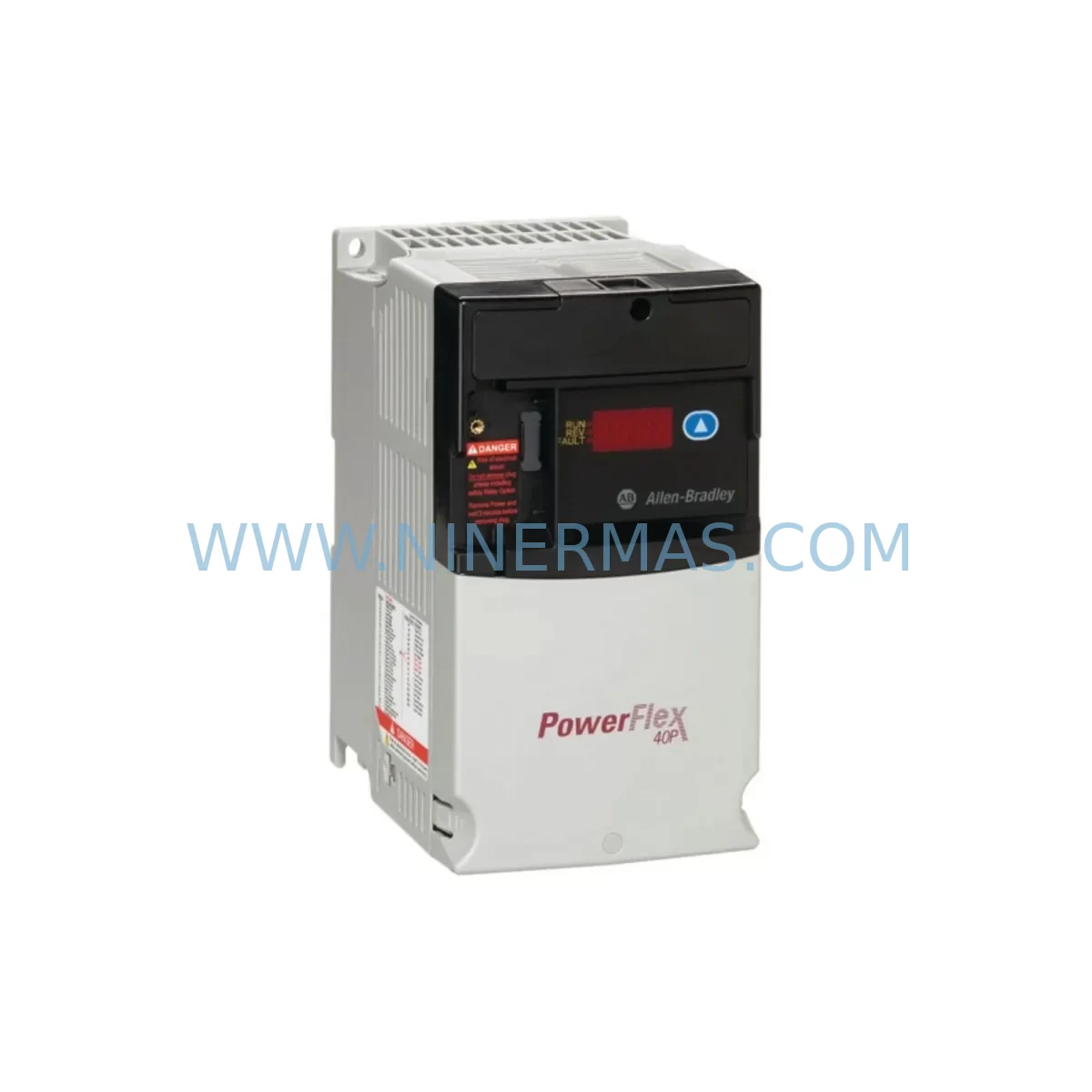
Allen-Bradley 22D-D012N104 Service-Ready Spare Part
Verify the part, confirm the platform family, and move straight into quotation with the right commercial details.
RFQ Ready
- SKU22D-D012N104
- CategoryPLC & Industrial Automation Modules
- BrandAllen-Bradley
- SupportAvailability, lead time, condition, and shipping coordination
How Buyers Usually Use This Page
- Confirm the exact part number and platform family before sending the quote request.
- Use direct email when quantity, condition, and destination are already defined internally.
- Switch to the broader brand or category archive when you need alternates nearby.
Series Navigation
Move through the most common platform families behind this part.
Product RFQ
Send this part directly for quotation.
Include quantity, required condition, destination country, and target delivery timing. Current reference: Allen-Bradley 22D-D012N104 Service-Ready Spare Part with SKU 22D-D012N104.
Allen-Bradley 22D-D012N104 Service-Ready Spare Part for Industrial Maintenance
The Allen-Bradley 22D-D012N104 is a PowerFlex 40 series AC variable frequency drive rated at 5.5 kW / 7.5 HP for 480V three-phase input, delivering 12A continuous output current. Designed for demanding industrial environments, this drive is widely deployed in conveyor systems, pump stations, fan arrays, compressor skids, and general-purpose motor control applications across manufacturing, water treatment, and process automation facilities. As a service-ready spare part sourced through NINERMAS, each unit undergoes pre-shipment functional verification to ensure drop-in compatibility with existing PowerFlex 40 installations — minimising commissioning time and reducing unplanned downtime risk.
Maintaining a stocked 22D-D012N104 in your spare parts inventory is a proven strategy for maintenance engineers managing aging automation infrastructure. PowerFlex 40 drives are embedded in thousands of legacy control cabinets worldwide, and lead times for new procurement can extend from weeks to months depending on regional availability. A pre-qualified replacement unit on the shelf converts a potential multi-day production stoppage into a same-shift recovery.
Spare Maintenance Table
| Parameter | Specification |
|---|---|
| SKU / Catalog Number | 22D-D012N104 |
| Series | PowerFlex 40 |
| Brand | Allen-Bradley (Rockwell Automation) |
| Output Power | 5.5 kW / 7.5 HP |
| Input Voltage | 480V AC, Three-Phase |
| Output Current (Continuous) | 12.0 A |
| Input Frequency | 47–63 Hz |
| Control Method | Sensorless Vector / V/Hz |
| Enclosure Rating | IP20 / NEMA Type 1 |
| Ambient Temperature | 0°C to +50°C (operating) |
| Communication Options | DSI port; optional DeviceNet, EtherNet/IP, PROFIBUS via adapter |
| Mounting | Panel / DIN rail compatible |
| Compatibility | Direct replacement for 22D-D012N104 in PowerFlex 40 installations |
| Certifications | UL, CE, RCM |
| Warranty | 12 Months — NINERMAS Quality Guarantee |
| Pre-Shipment Testing | Functional verification completed before dispatch |
| Typical Application | Conveyors, pumps, fans, compressors, general motor control |
Maintenance Planning for Continuous Operation
When a 22D-D012N104 drive trips or fails in service, the fault rarely exists in isolation. Experienced maintenance engineers treat a drive replacement as an opportunity to audit the surrounding electrical circuit and control cabinet for latent issues that could trigger a repeat failure within weeks. A structured inspection of the following components is strongly recommended before and after installing the replacement unit.
Input power quality is the first checkpoint. Verify the upstream 480V supply using a power quality analyser — voltage imbalance exceeding 2% between phases will shorten drive IGBT life significantly. Check the input line reactor or EMC filter (such as the 1321-3R series line reactor commonly paired with PowerFlex 40 drives) for signs of overheating or insulation degradation. Blown or weakened input fuses in the MCC or distribution panel should be replaced as a matter of course.
Motor cable integrity is the second priority. Excessive cable length or unshielded runs between the drive and motor can generate reflected wave voltages that stress the drive output stage. Inspect the motor cable for insulation damage, verify shield continuity, and confirm that a load-side output reactor or dV/dt filter is installed where cable runs exceed 30 metres. The motor itself should be tested for winding insulation resistance (megger test) before reconnection — a degraded motor winding is a common root cause of repeated drive overcurrent faults.
Control wiring and I/O terminals deserve careful attention. Loose or corroded connections on the 22D-D012N104 terminal block — particularly on the digital input terminals (DI1–DI6), analog input (0–10V / 4–20mA), and relay output — can cause intermittent faults that are difficult to diagnose. Clean and re-torque all control terminals to specification. If the drive is integrated into a PLC-controlled system via a 22-COMM-E EtherNet/IP adapter or a 22-COMM-D DeviceNet adapter, verify adapter firmware version compatibility and inspect the DSI ribbon cable for damage.
Safety and protection components in the same cabinet should be inspected in parallel. Safety relays (such as the Guardmaster 440R series) that interface with the drive’s enable input should be tested for correct operation. Thermal overload relays on the motor branch circuit, surge protection devices (SPDs) on the incoming supply, and any 24VDC control power supply (such as the 1606-XLP series) feeding the drive’s control logic should all be verified for correct output voltage and thermal condition.
HMI and operator interface connectivity should be confirmed after drive replacement. If a PanelView 800 or PanelView Plus terminal is used for drive parameter monitoring, verify that the communication link is re-established and that drive parameters are correctly loaded — either from a backup parameter file or via the 22-HIM-A3 handheld programmer. Documenting the parameter set before removing the failed drive is a critical step that is frequently overlooked under time pressure.
Backplane and rack integrity applies where the PowerFlex 40 is installed alongside a ControlLogix or CompactLogix PLC rack. Inspect the 1756-A series backplane connectors and the 1756-PA75 or 1756-PB75 power supply for signs of overheating. A failing rack power supply can cause erratic drive behaviour that mimics a drive fault.
Maintaining a minimum stock of one 22D-D012N104 per production line — alongside a 22-COMM-E adapter, a spare 22-HIM-A3 programmer, and a set of input fuses — is a practical inventory strategy that supports a target mean-time-to-repair (MTTR) of under four hours for drive-related stoppages.
Site Replacement Workflow
Step 1 — Isolation and lockout/tagout (LOTO): De-energise the drive at the upstream MCC or disconnect switch. Verify absence of voltage at the drive input terminals using a calibrated CAT III multimeter. Allow a minimum of five minutes for the DC bus capacitors to discharge before opening the enclosure.
Step 2 — Parameter backup: If the existing drive is still partially functional, connect the 22-HIM-A3 handheld programmer and upload the full parameter set. Record the motor nameplate data, acceleration/deceleration ramp times, speed reference source, and any custom fault response configurations. This data is essential for commissioning the replacement unit to identical operating conditions.
Step 3 — Physical removal: Photograph the control wiring layout before disconnecting any terminals. Label each wire with its terminal designation. Remove the drive from the panel mounting rail, noting the torque values for any DIN rail clips or mounting screws.
Step 4 — Inspection of mounting location: Before installing the 22D-D012N104 replacement, inspect the mounting surface for heat discolouration, which may indicate inadequate ventilation. Verify that the minimum clearance distances specified in the PowerFlex 40 User Manual (publication 22B-UM001) are maintained — 50mm top and bottom, 25mm sides for IP20 units.
Step 5 — Installation and wiring: Mount the replacement drive and reconnect power and control wiring in reverse order of removal, referencing the photographs taken in Step 3. Torque all power terminals to the specified values (typically 1.1–1.3 Nm for the 22D-D012N104 power terminals). Reconnect the DSI communication adapter if applicable.
Step 6 — Parameter restore and commissioning: Download the saved parameter set to the replacement drive using the 22-HIM-A3. Perform a motor auto-tune routine to optimise sensorless vector performance with the connected motor. Verify all digital inputs, analog references, and relay outputs before returning the drive to automatic control.
Step 7 — Test run and handover: Run the drive at low speed (10–15 Hz) under no-load conditions first, then progressively load to full operating speed. Monitor output current, DC bus voltage, and heatsink temperature for the first 30 minutes of operation. Document the replacement in the equipment maintenance log and update the spare parts inventory record.
Spare Parts Support FAQ
Q1: Is the NINERMAS 22D-D012N104 a direct drop-in replacement for the original Allen-Bradley unit?
Yes. The 22D-D012N104 supplied by NINERMAS is sourced to the original Allen-Bradley catalog specification and is a direct physical and electrical replacement for existing PowerFlex 40 installations. No hardware modification is required. Parameter configuration is handled during commissioning using the standard 22-HIM-A3 programmer or RSLogix 500/Studio 5000 software.
Q2: What pre-shipment testing is performed on each unit?
Every 22D-D012N104 unit undergoes functional power-on verification prior to dispatch. This includes input voltage application, DC bus charge confirmation, output switching test, and communication port integrity check. A test record is retained for each unit. Units that do not pass verification are not shipped.
Q3: What warranty and long-term supply commitment does NINERMAS offer?
All units carry a 12-month warranty from the date of shipment, covering manufacturing defects and functional failures under normal operating conditions. NINERMAS maintains a dedicated stock programme for PowerFlex 40 series components to support long-term procurement planning. Customers with recurring maintenance requirements are encouraged to contact our team to discuss volume reservation and scheduled delivery arrangements.
Q4: How do I verify compatibility if my existing drive has a different firmware or option card configuration?
The 22D-D012N104 catalog number defines the base drive hardware. Communication adapters (22-COMM-E, 22-COMM-D, 22-COMM-P) and the handheld programmer (22-HIM-A3) are field-installable accessories that are independent of the base drive firmware. If your application requires a specific firmware version, please provide your existing drive nameplate details when placing your order and our technical team will confirm compatibility before shipment.
| Product Series | PowerFlex |
|---|---|
| Country of Origin | US |
Catalog Continuation
More Allen-Bradley modules in the catalog.
Use the brand lane to compare nearby part numbers, platform-adjacent modules, and other inquiry-ready listings before sending your final RFQ.
Catalog Continuation
Alternative parts within PLC & Industrial Automation Modules.
Stay inside the same system family when you need substitutes, adjacent modules, or a broader shortlist for procurement review.
SKU: PCE-2 LIF-1 K15MB000 671-5532-02
Tektronix PCE-2 LIF-1 K15MB000 671-5532-02 Service-Ready Spare Part