Original Industrial Spare Part
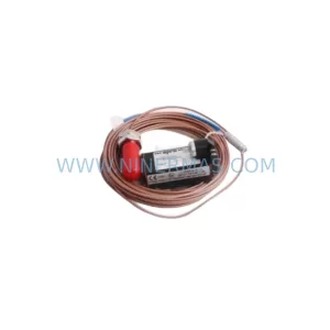
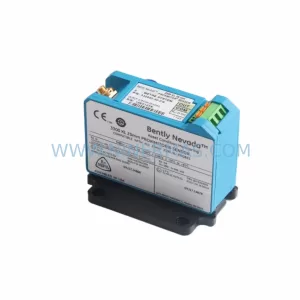
Bently Nevada 190501-06-00-04 Retrofit Velocity Transducer
Verify the part, confirm the platform family, and move straight into quotation with the right commercial details.
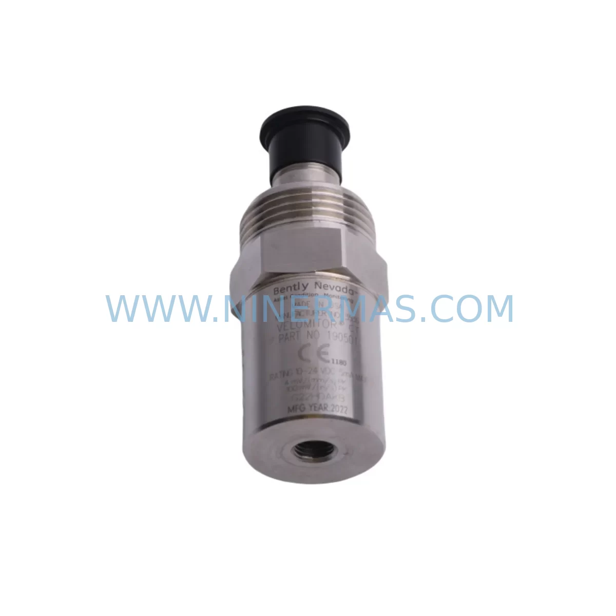
RFQ Ready
- SKU190501-06-00-04
- CategoryTSI & Rotating Machinery Monitoring
- BrandBently Nevada
- SupportAvailability, lead time, condition, and shipping coordination
How Buyers Usually Use This Page
- Confirm the exact part number and platform family before sending the quote request.
- Use direct email when quantity, condition, and destination are already defined internally.
- Switch to the broader brand or category archive when you need alternates nearby.
Series Navigation
Move through the most common platform families behind this part.
Product RFQ
Send this part directly for quotation.
Include quantity, required condition, destination country, and target delivery timing. Current reference: Bently Nevada 190501-06-00-04 Retrofit Velocity Transducer with SKU 190501-06-00-04.
Bently Nevada 190501-06-00-04 Retrofit Velocity Transducer: Legacy System Compatible Upgrade
The Bently Nevada 190501-06-00-04 is a ruggedized velocity transducer engineered for continuous vibration monitoring in demanding industrial environments. As original equipment reaches end-of-life and spare parts become increasingly scarce, this module serves as a direct retrofit-compatible replacement for aging Bently Nevada monitoring architectures — enabling plant engineers to restore system integrity without redesigning the entire control infrastructure.
Whether you are managing a turbine protection panel, a compressor monitoring rack, or a rotating machinery surveillance system built on legacy Bently Nevada hardware, the 190501-06-00-04 provides a reliable, field-proven path to extend operational life while maintaining measurement accuracy and system continuity. Its ruggedized construction makes it suitable for high-vibration, high-temperature, and chemically aggressive plant environments where standard transducers would fail prematurely.
Upgrade Compatibility Table
| Parameter | Details |
|---|---|
| SKU / Part Number | 190501-06-00-04 |
| Brand / Series | Bently Nevada / 190501 Velocity Transducer Series |
| Transducer Type | Ruggedized Velocity (Seismic) |
| Typical Application | Turbine, compressor, pump, and motor vibration monitoring |
| Mounting Interface | Compatible with standard Bently Nevada mounting adapters and legacy bracket configurations |
| Signal Output | Velocity (mV/mm/s or mV/in/s per system configuration) |
| Communication Compatibility | Passive analog output; compatible with 3300 Series monitors, 3500 Series rack I/O, and equivalent signal conditioners |
| Replacement Suitability | Direct replacement for discontinued 190501 variants; verify cable connector type and sensitivity range before installation |
| Installation Space | Confirm clearance at measurement point; ruggedized housing may require adapter for tight-space installations |
| Commissioning Notes | Verify polarity, sensitivity calibration, and monitor channel scaling after replacement |
| Warranty | 12-Month Warranty — covers manufacturing defects under normal operating conditions |
Retrofit Planning for Existing Automation Systems
Successful integration of the 190501-06-00-04 into an existing monitoring system begins with a thorough audit of the current installation. Engineers should document the existing transducer’s cable routing, connector type, and sensitivity specification before ordering a replacement. In most legacy Bently Nevada installations, the transducer connects to a 3300 Series monitor or a 3500/22M Transient Data Interface module housed in a standard 19-inch rack. Confirming that the replacement transducer’s sensitivity (typically expressed in mV/mm/s) matches the monitor’s configured input range is critical to avoid false alarms or missed trips after changeover.
For plants running a 3500 Series rack, the 190501-06-00-04 feeds signal into the rack’s I/O modules — such as the 3500/42M Proximitor/Seismic Monitor — which processes the velocity signal and compares it against configured alert and danger setpoints. If the rack also includes a 3500/20 Rack Interface Module (RIM) for Modbus or Ethernet/IP communication to the DCS or SCADA layer, engineers must verify that the channel configuration in the rack’s software (System 1 or Rack Configuration Software) correctly reflects the new transducer’s parameters after replacement.
In older installations where the monitoring rack communicates via a 3500/92 Communication Gateway using legacy serial protocols, the retrofit plan should include a protocol compatibility check to ensure the upstream historian or DCS continues to receive valid vibration data without requiring a full communication reconfiguration. Where plants are simultaneously upgrading from serial to Ethernet-based communication, the transducer replacement can be coordinated with the installation of a 3500/93 Communication Gateway to modernize the data path in a single planned outage window.
Beyond the monitoring rack, engineers should inspect the field junction box and cable terminations. The 190501-06-00-04‘s cable connector must be verified against the existing field wiring — particularly the shield grounding arrangement, which directly affects signal quality in electrically noisy environments such as motor control centers or variable frequency drive (VFD) enclosures. Where cable lengths exceed recommended limits, a signal isolator or barrier module may be required to maintain signal integrity between the transducer and the monitor input.
For plants that also operate Keyphasor transducers (such as the 330980 Proximity Transducer System) in the same machinery train, the retrofit plan should confirm that the Keyphasor signal remains stable and correctly phased after the velocity transducer replacement, as some 3500 Series monitors use the Keyphasor reference for phase-referenced vibration analysis. If the existing 3300/16 Velocity Monitor is also approaching end-of-life, a coordinated replacement of both the transducer and the monitor card during the same planned shutdown minimizes total downtime and reduces the risk of a second unplanned outage shortly after the first.
Where the control system includes a Bently Nevada System 1 Evolution software platform for online machinery diagnostics, the new transducer’s channel must be reconfigured in the software database to reflect the correct sensitivity, engineering units, and full-scale range. This step is often overlooked during rushed retrofits and can result in incorrect trend data or missed alarm conditions in the weeks following the changeover.
Downtime Control During System Migration
Minimizing unplanned downtime is the primary concern for any maintenance team undertaking a velocity transducer replacement on a running production line. The recommended approach is to pre-stage the 190501-06-00-04 replacement unit alongside all required tools, adapters, and cable connectors before the planned maintenance window opens. A pre-installation bench test — verifying the transducer’s output sensitivity using a calibrated shaker or reference signal source — confirms the unit is functional before it reaches the field, eliminating the risk of installing a defective part during a time-critical outage.
During the replacement, the existing monitor channel should be placed in bypass mode (where the 3500 Series rack supports this function) to prevent spurious trips to the safety system while the transducer is disconnected. The original program logic in the DCS or safety PLC should not be modified during the transducer swap — only the physical field device and its termination are changed. After reconnection, the channel should be brought out of bypass incrementally, with a live signal check confirming that the monitor is receiving a valid velocity reading within the expected range before the bypass is fully removed.
For critical machinery where even a brief monitoring gap is unacceptable, a temporary portable vibration monitor can be connected in parallel during the replacement to maintain continuous surveillance of the machine’s vibration signature. This approach is particularly valuable on high-speed turbines or compressors where a sudden change in vibration level during the maintenance window could indicate a developing mechanical fault unrelated to the transducer replacement itself.
All wiring changes, sensitivity settings, and post-installation test results should be documented in the plant’s maintenance management system (CMMS) immediately after the retrofit is complete. This record supports future troubleshooting, audit compliance, and warranty claims under the included 12-month warranty coverage.
Retrofit Support FAQ
Q1: Is the 190501-06-00-04 a direct drop-in replacement for other discontinued 190501 series variants?
In most cases, yes — the 190501 series shares a common mechanical form factor and signal output type across variants. However, the specific sensitivity rating (mV/mm/s) and connector configuration must be verified against the existing installation before ordering. Our technical team can assist with cross-reference confirmation based on your existing part number and monitor model.
Q2: What wiring checks are required before powering up after replacement?
Verify shield grounding continuity, confirm correct polarity at the monitor input terminals, and check that the cable connector is fully seated and locked. For installations near VFDs or high-voltage switchgear, inspect the cable routing for proximity to interference sources and re-route if necessary. A loop resistance check between the transducer and the monitor input is also recommended before energizing.
Q3: How do I confirm compatibility with my existing 3500 Series monitor configuration?
Open the rack’s configuration software and review the channel setup for the affected monitor module. Confirm that the configured transducer type, sensitivity, and engineering units match the 190501-06-00-04 specifications. If the channel was previously configured for a different sensitivity value, update the configuration and download it to the rack before bringing the channel out of bypass.
Q4: What does the 12-month warranty cover, and how is it claimed?
The 12-month warranty covers manufacturing defects and functional failures under normal operating conditions as specified in the product datasheet. It does not cover damage resulting from incorrect installation, overvoltage, or mechanical impact. To initiate a warranty claim, contact our support team with the original order reference, installation date, and a description of the observed fault. Units confirmed defective under warranty will be replaced or repaired at no additional charge.
| Product Series | 3300 series |
|---|---|
| Country of Origin | US |
Catalog Continuation
More Bently Nevada modules in the catalog.
Use the brand lane to compare nearby part numbers, platform-adjacent modules, and other inquiry-ready listings before sending your final RFQ.
SKU: 330194-13-20-10-00
Bently Nevada 330194-13-20-10-00 Safety-Reliable Monitor for Critical Control
SKU: 330701-00-40-10-11-05
Bently Nevada 330701-00-40-10-11-05 Safety Vibration Monitor
SKU: 21000-33-05-00-035-03-02
Bently Nevada 21000-33-05-00-035-03-02 Safety Relay
Catalog Continuation
Alternative parts within TSI & Rotating Machinery Monitoring.
Stay inside the same system family when you need substitutes, adjacent modules, or a broader shortlist for procurement review.