Original Industrial Spare Part
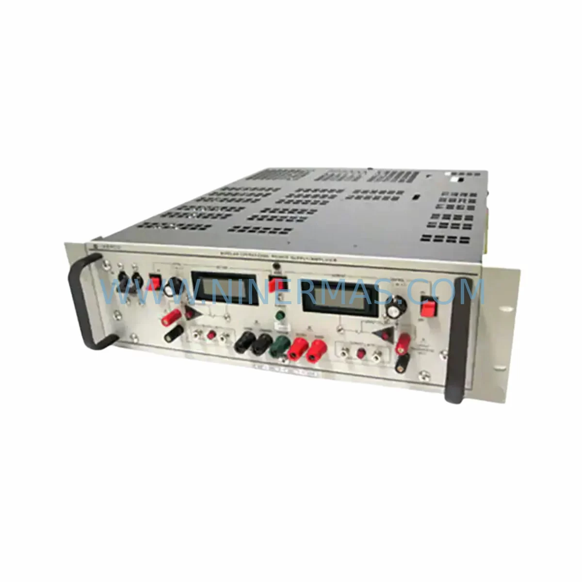
KEPCO BOP-20-20M Retrofit-Compatible Bipolar Power Supply
Verify the part, confirm the platform family, and move straight into quotation with the right commercial details.
RFQ Ready
- SKUBOP-20-20M
- CategoryPLC & Industrial Automation Modules
- BrandKEPCO
- SupportAvailability, lead time, condition, and shipping coordination
How Buyers Usually Use This Page
- Confirm the exact part number and platform family before sending the quote request.
- Use direct email when quantity, condition, and destination are already defined internally.
- Switch to the broader brand or category archive when you need alternates nearby.
Series Navigation
Move through the most common platform families behind this part.
Product RFQ
Send this part directly for quotation.
Include quantity, required condition, destination country, and target delivery timing. Current reference: KEPCO BOP-20-20M Retrofit-Compatible Bipolar Power Supply with SKU BOP-20-20M.
KEPCO BOP-20-20M Retrofit-Compatible Bipolar Power Supply for Legacy Automation Systems
The KEPCO BOP-20-20M is a high-performance bipolar operational power supply (BOP) designed for seamless integration into existing automation and test systems where legacy BOP Series units are being retired, replaced, or upgraded. With a rated output of ±20V / ±20A and true 4-quadrant operation, the BOP-20-20M serves as a direct retrofit replacement for discontinued BOP Series models, enabling engineers to restore full system functionality without redesigning control cabinet wiring or reprogramming upstream controllers.
For facilities managing aging test benches, motor simulation rigs, or precision process control loops, the BOP-20-20M delivers the same bipolar output characteristics as its predecessors while offering improved stability, tighter load regulation, and compatibility with modern GPIB (IEEE-488) and RS-232 communication interfaces. This makes it an ideal candidate for protocol migration projects where legacy instrumentation buses are being consolidated or upgraded to current standards.
Upgrade Compatibility Table
| Parameter | Details |
|---|---|
| SKU / Model | BOP-20-20M |
| Brand / Series | KEPCO / BOP Series |
| Output Voltage | ±20V (Bipolar) |
| Output Current | ±20A (Bipolar) |
| Operation Mode | 4-Quadrant (Source & Sink) |
| Communication Interface | GPIB (IEEE-488), RS-232 (model-dependent) |
| Mounting / Form Factor | Rack-mount, standard 19″ chassis |
| Replacement Compatibility | Direct retrofit for legacy BOP-20-20D and BOP Series predecessors |
| Terminal / Connector | Rear-panel binding posts; verify existing cable lug sizing before installation |
| Installation Space | Confirm rack unit (U) clearance and rear cable management depth |
| Commissioning Notes | Verify GPIB address assignment; re-run calibration routine post-installation |
| Warranty | 12 Months — covers parts and workmanship from date of shipment |
Retrofit Planning for Existing Automation Systems
When integrating the BOP-20-20M into an existing control architecture, the retrofit process typically begins with a thorough audit of the power distribution panel and control cabinet layout. Engineers must confirm that the available AC mains capacity — typically 115V or 230V single-phase — matches the BOP-20-20M input specification, and that the existing circuit breaker rating accommodates the unit’s inrush and steady-state current draw. In multi-instrument racks where the BOP-20-20M shares rail space with other KEPCO power modules such as the MBC or ABC Series mainframes and their plug-in modules, careful attention to thermal spacing and airflow direction is essential to prevent derating.
Terminal wiring is a critical checkpoint. The BOP-20-20M uses rear-panel binding posts for output connections. If the legacy unit used a different terminal block style — such as screw-cage terminals common on older European-sourced power supplies — adaptor lugs or new cable assemblies will be required. Polarity labeling on the existing wiring harness should be verified against the BOP-20-20M output polarity convention before energizing the system.
For systems where the BOP-20-20M is controlled via GPIB bus alongside other instruments — such as KEPCO BIT 4886 IEEE-488 interface cards, digital multimeters, or programmable loads — the GPIB primary address must be set on the BOP-20-20M front panel to avoid bus conflicts. If the control software was written for an older BOP model, the SCPI command set should be reviewed for compatibility; most BOP Series units share a common command structure, but firmware-level differences in status byte reporting or error queue handling may require minor software updates.
In systems that include signal isolation requirements — for example, where the BOP-20-20M output is referenced to a floating ground or where the load is a sensitive electrochemical cell — signal isolators or differential amplifier modules may be inserted between the BOP-20-20M sense terminals and the measurement chain. Similarly, if the retrofit involves migrating from analog programming (0–10V or 4–20mA control signals) to digital GPIB control, the existing analog signal conditioning circuitry — including signal isolators, D/A converters, and shielded cabling — can typically be decommissioned, simplifying the cabinet layout.
Where the BOP-20-20M is part of a larger test system managed by a PC-based controller running LabVIEW, MATLAB, or a custom SCPI driver, the instrument driver library should be updated to reference the BOP-20-20M model string. KEPCO provides IVI-compliant drivers that are compatible with most modern test executive environments, reducing integration time significantly compared to writing custom low-level GPIB routines.
Downtime Control During System Migration
Minimizing production or test downtime during a BOP-20-20M retrofit requires a structured changeover plan. The recommended approach is to pre-configure and bench-test the BOP-20-20M — including GPIB address assignment, output limit programming, and calibration verification — before the scheduled maintenance window. This allows the physical swap to be completed within a single shift, with the system returning to operational status the same day.
Where continuous process control is required and a cold swap is not acceptable, a parallel commissioning strategy can be employed: the BOP-20-20M is installed in an adjacent rack slot and brought online in a shadow mode, with its output monitored against the legacy unit before the final cutover. This approach is particularly valuable in electrochemical process lines, motor characterization rigs, or battery cycling systems where output continuity directly affects product quality or test data integrity.
Original program logic — whether stored in a PC-based test executive, a PLC, or a standalone controller — does not need to be rewritten for a like-for-like BOP Series replacement. The SCPI command structure is preserved across BOP generations, meaning that existing test sequences, ramp profiles, and protection limit settings can be transferred directly. HMI screens that display BOP output status via GPIB polling will continue to function without modification, provided the GPIB address is matched to the legacy unit’s setting.
Post-installation, a structured commissioning checklist should include: output voltage and current calibration verification at zero, mid-scale, and full-scale; protection limit trip testing; GPIB communication handshake confirmation; and a 30-minute thermal soak at rated load to confirm stable operation before returning the system to production. All units supplied by NINERMAS are pre-tested prior to shipment and covered by a 12-month warranty from the date of delivery.
Retrofit Support FAQ
Q1: Is the BOP-20-20M a direct drop-in replacement for the BOP-20-20D?
The BOP-20-20M and BOP-20-20D share the same output ratings (±20V / ±20A) and chassis form factor, making the BOP-20-20M a functionally compatible retrofit replacement in most applications. The primary difference is the programming interface: the BOP-20-20M designation typically indicates a specific interface option (e.g., analog programming). Confirm the interface suffix of your legacy unit against the BOP-20-20M specification sheet before ordering to ensure full compatibility.
Q2: What commissioning steps are required after installation?
After physical installation, set the GPIB primary address to match the legacy unit’s address (or update the control software if a new address is preferred). Run the built-in calibration routine as described in the BOP-20-20M operator manual. Verify output polarity at the load terminals before connecting sensitive equipment. Confirm protection limits (OVP, OCP) are programmed to appropriate values for your application. A full-load burn-in test of 30–60 minutes is recommended before returning the system to service.
Q3: Can the BOP-20-20M be used with existing GPIB cables and controllers?
Yes. The BOP-20-20M is fully IEEE-488.2 compliant and compatible with standard GPIB cables and any GPIB controller card (e.g., National Instruments GPIB-USB-HS or PCI-GPIB). No special cabling or interface adapters are required. If your system uses RS-232 control, verify the interface option on the BOP-20-20M model suffix to confirm RS-232 is included.
Q4: What is the warranty coverage and what does NINERMAS provide for stock supply?
All BOP-20-20M units supplied by NINERMAS carry a 12-month warranty covering manufacturing defects and workmanship from the date of shipment. Units are pre-tested and inspected before dispatch. NINERMAS maintains inventory of BOP Series spare parts to support long-term procurement planning for facilities managing legacy test systems. For volume orders or long-term supply agreements, contact our sales team directly to discuss lead times and stock commitment options.
| Product Series | Other series |
|---|
Catalog Continuation
Alternative parts within PLC & Industrial Automation Modules.
Stay inside the same system family when you need substitutes, adjacent modules, or a broader shortlist for procurement review.
SKU: TTLM10-11 ELVIF-F 3895-120321-21 TTLD14-12 WCIF-L 3881-020032-11 TTLM11-11 W/TIF-L 3895-120322-21
TEL 3895-120321-21 Service-Ready Spare for Industrial Maintenance
SKU: KR6 00-204-935 00-204-551
KUKA KR6 00-204-935 00-204-551 Retrofit-Compatible Signal Cable for Legacy Systems