Original Industrial Spare Part
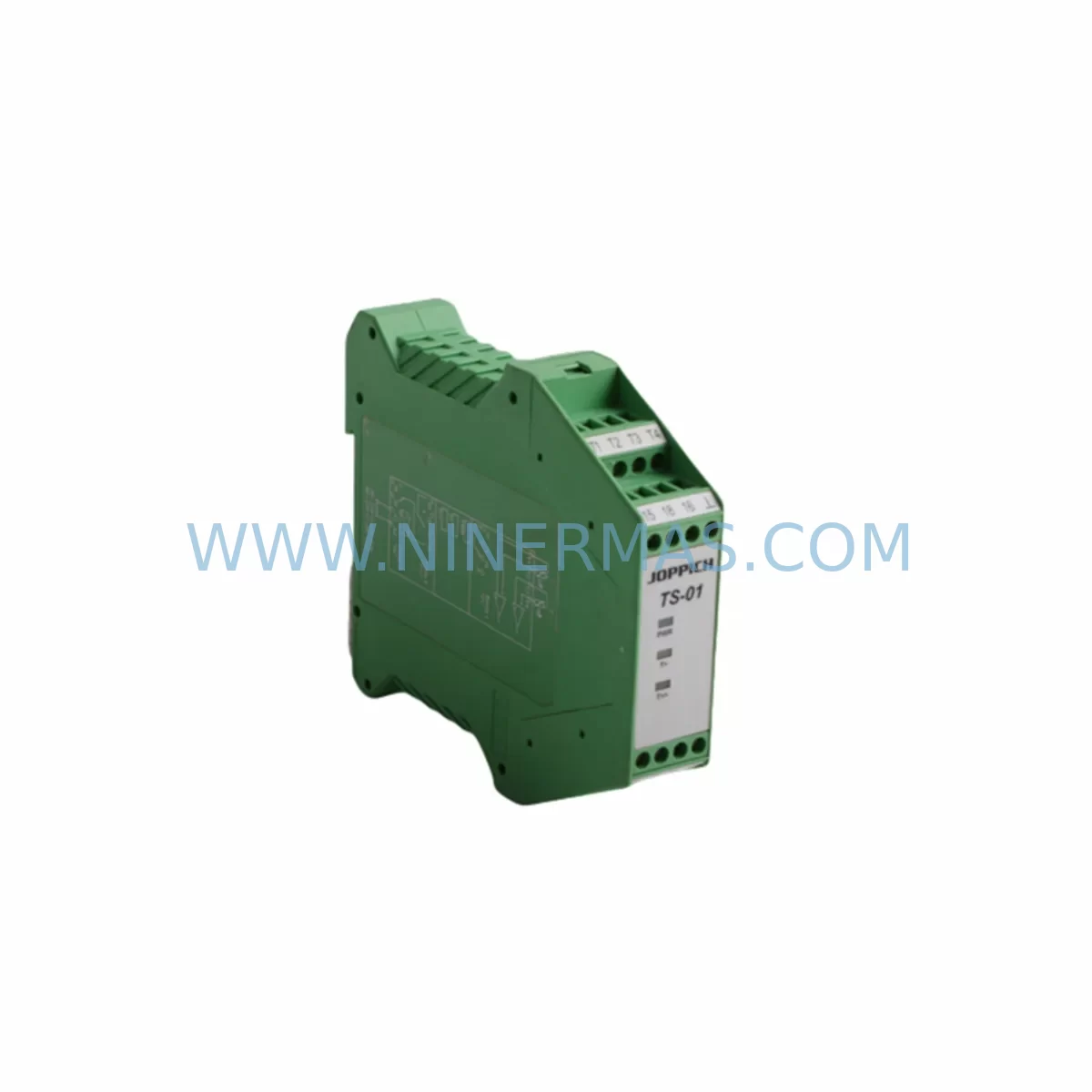
JOPPICH TS-01 Retrofit-Compatible Temp Sensor
Verify the part, confirm the platform family, and move straight into quotation with the right commercial details.
RFQ Ready
- SKUTS-01
- CategoryPLC & Industrial Automation Modules
- BrandJOPPICH
- SupportAvailability, lead time, condition, and shipping coordination
How Buyers Usually Use This Page
- Confirm the exact part number and platform family before sending the quote request.
- Use direct email when quantity, condition, and destination are already defined internally.
- Switch to the broader brand or category archive when you need alternates nearby.
Series Navigation
Move through the most common platform families behind this part.
Product RFQ
Send this part directly for quotation.
Include quantity, required condition, destination country, and target delivery timing. Current reference: JOPPICH TS-01 Retrofit-Compatible Temp Sensor with SKU TS-01.
JOPPICH TS-01 Retrofit-Compatible Temperature Sensor for Legacy Automation Systems
The JOPPICH TS-01 is a retrofit-compatible temperature sensing module engineered for seamless integration into aging industrial control architectures. As legacy temperature monitoring systems reach end-of-life and OEM spare parts become increasingly scarce, the TS-01 provides a reliable, drop-in-compatible upgrade path that preserves existing wiring infrastructure, minimizes downtime, and extends the operational life of your control cabinet without requiring a full system overhaul.
Designed for engineers and maintenance teams managing legacy PLC platforms, the TS-01 supports standard thermocouple and RTD input types commonly found in discontinued temperature monitoring series. Its compact DIN-rail form factor fits within existing control cabinet layouts, and its signal output range is compatible with analog input modules from major automation platforms — reducing the need for signal conditioning adapters or intermediate converters during retrofit projects.
Upgrade Compatibility Table
| Parameter | Legacy Reference | JOPPICH TS-01 | Retrofit Notes |
|---|---|---|---|
| Input Type | Thermocouple / RTD (PT100) | Thermocouple (J/K/T/E) + PT100/PT1000 | Verify input type before wiring; jumper-selectable on TS-01 |
| Output Signal | 4–20 mA / 0–10 V | 4–20 mA / 0–10 V (selectable) | Match to existing AI module input range |
| Supply Voltage | 24 VDC | 18–30 VDC | Confirm PSU capacity; JOPPICH PS-24 power supply recommended |
| Mounting | 35 mm DIN Rail | 35 mm DIN Rail | Direct replacement; no bracket modification required |
| Terminal Type | Screw terminal (2.5 mm²) | Screw terminal (2.5 mm²) | Existing field wiring can be reused |
| Communication | Analog only | Analog + optional HART | HART enables remote diagnostics without additional wiring |
| Installation Space | ~22.5 mm width | 22.5 mm width | Fits standard control cabinet rail allocation |
| Commissioning | Manual calibration | Auto-calibration via front panel or HART | Reduces on-site commissioning time significantly |
| Warranty | OEM EOL — no support | 12-Month Warranty | Covered from date of shipment; includes functional test certificate |
Retrofit Planning for Existing Automation Systems
Successful integration of the JOPPICH TS-01 into a legacy control system begins with a thorough pre-retrofit audit. Before removing the existing temperature transmitter, document the current terminal wiring layout, confirm the supply voltage from the control cabinet’s 24 VDC power rail, and verify the analog input channel assignment on the connected PLC analog input module — such as a Siemens SM 331 or equivalent legacy AI card. This ensures the TS-01’s 4–20 mA output is correctly mapped to the existing process variable tag in the PLC program without requiring software re-engineering.
In systems where the temperature loop feeds into an HMI display — for example, a SIMATIC OP or TP panel — confirm that the engineering unit scaling (e.g., 0–500 °C mapped to 4–20 mA) is preserved in the HMI tag configuration. The TS-01’s output linearity and zero/span calibration are factory-set, but field verification using a loop calibrator is recommended before returning the loop to automatic control.
For control cabinets that house multiple temperature channels — common in multi-zone furnace control, extruder temperature management, or HVAC plant rooms — the TS-01 can be installed in sequence alongside existing modules on the same DIN rail. If the cabinet also contains a JOPPICH RM-16 relay module or a third-party safety relay for over-temperature protection, verify that the TS-01’s output signal range is compatible with the relay’s analog trip threshold input. In systems using a Profibus DP or Modbus RTU communication backbone, a JOPPICH GW-MB gateway or equivalent protocol converter may be used to bring the TS-01’s HART signal into the digital communication layer without disrupting the existing fieldbus topology.
Where the legacy system includes a signal isolator or barrier — such as a Pepperl+Fuchs KFD2 series or equivalent intrinsic safety barrier — confirm that the TS-01’s output impedance and loop current characteristics are within the barrier’s specified load range. In most cases, the TS-01’s 4–20 mA two-wire or four-wire configuration can be adapted to the existing barrier wiring with minor terminal reassignment. Spare terminal blocks and DIN rail end stops should be prepared in advance to maintain a clean, compliant installation.
For systems undergoing a broader control platform migration — for example, transitioning from a legacy S5 or S7-300 rack to a modern S7-1500 or equivalent controller — the TS-01 provides a stable analog front-end that remains compatible across both generations. This allows temperature sensing infrastructure to be retained while the controller backplane, CPU module, and communication processor are upgraded in a phased approach, reducing the scope and risk of each maintenance window.
Downtime Control During System Migration
Minimizing production downtime during a temperature sensor replacement requires careful sequencing of the cutover procedure. The recommended approach is to pre-wire the JOPPICH TS-01 on a temporary terminal strip adjacent to the existing transmitter, verify its output signal against a reference instrument, and only then transfer the field wiring from the old device to the new one — a process that typically takes under 15 minutes per channel when the cabinet is properly documented.
Where the temperature loop is part of a closed-loop PID control strategy, place the controller in manual mode before disconnecting the existing sensor. This prevents the PLC from responding to a spurious process variable reading during the changeover and protects downstream actuators — such as control valves, heater contactors, or cooling fans — from unintended operation. Once the TS-01 is wired and powered, confirm the live reading against a calibrated reference thermometer before returning the loop to automatic mode.
For multi-channel systems where several TS-01 units are being installed simultaneously, a channel-by-channel replacement strategy is preferred over a full shutdown. This approach maintains partial process visibility throughout the migration and allows the maintenance team to validate each channel independently before proceeding to the next. Detailed loop test records — including as-found and as-left readings, terminal assignments, and calibration data — should be completed for each channel and retained as part of the plant’s maintenance documentation.
NINERMAS provides pre-shipment functional testing for all TS-01 units, with a test certificate included in the delivery package. This eliminates the need for incoming inspection calibration and allows the replacement unit to be installed directly from the box, further reducing the time between receipt and return-to-service. Combined with our in-stock availability and same-day dispatch capability, the TS-01 supports rapid-response maintenance scenarios where extended downtime is not acceptable.
Retrofit Support FAQ
Q1: Is the JOPPICH TS-01 a direct replacement for my existing temperature transmitter?
The TS-01 is designed to be dimensionally and electrically compatible with a wide range of legacy DIN-rail-mounted temperature transmitters. In most cases, existing field wiring and terminal assignments can be reused without modification. We recommend confirming the input sensor type (thermocouple vs. RTD) and output signal range (4–20 mA vs. 0–10 V) against your existing loop documentation before ordering.
Q2: What commissioning steps are required after installation?
After mounting and wiring the TS-01, apply 24 VDC supply power and verify the output signal using a loop calibrator or multimeter. Confirm the zero and span calibration against a known reference temperature. If HART communication is used, connect a HART communicator or HART-enabled asset management system to verify device configuration and perform remote calibration if required. Return the PLC analog input channel to scan and confirm the process variable tag reads correctly in the SCADA or HMI system.
Q3: Does NINERMAS provide a warranty and functional test certificate?
Yes. Every JOPPICH TS-01 supplied by NINERMAS carries a 12-month warranty from the date of shipment, covering manufacturing defects and functional failures under normal operating conditions. A pre-shipment functional test certificate is included with each unit, confirming that the device has been tested against its published specification prior to dispatch.
Q4: What is the lead time and stock availability?
NINERMAS maintains in-stock inventory of the JOPPICH TS-01 to support urgent maintenance and planned retrofit projects. Same-day dispatch is available for orders confirmed before the daily cut-off time. For large-quantity requirements or long-term spare parts programs, contact our sales team to discuss dedicated stock allocation and scheduled delivery arrangements.
| Product Series | Other series |
|---|
Catalog Continuation
Alternative parts within PLC & Industrial Automation Modules.
Stay inside the same system family when you need substitutes, adjacent modules, or a broader shortlist for procurement review.
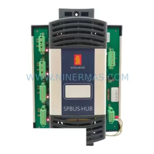
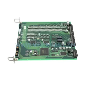
SKU: TTLM10-11 ELVIF-F 3895-120321-21 TTLD14-12 WCIF-L 3881-020032-11 TTLM11-11 W/TIF-L 3895-120322-21
TEL 3895-120321-21 Service-Ready Spare for Industrial Maintenance
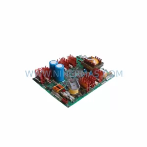
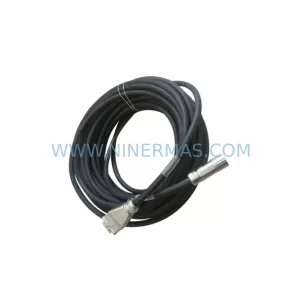
SKU: KR6 00-204-935 00-204-551
KUKA KR6 00-204-935 00-204-551 Retrofit-Compatible Signal Cable for Legacy Systems