Original Industrial Spare Part
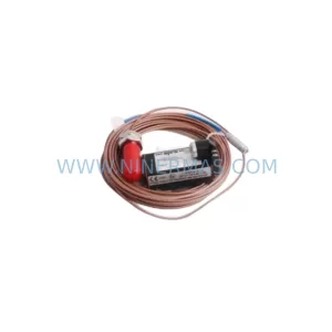
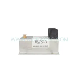
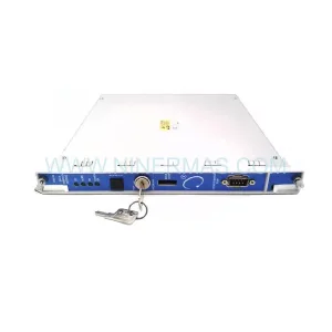
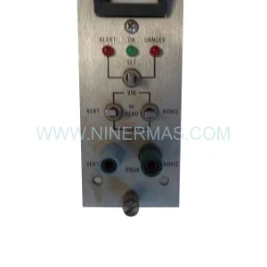
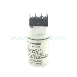
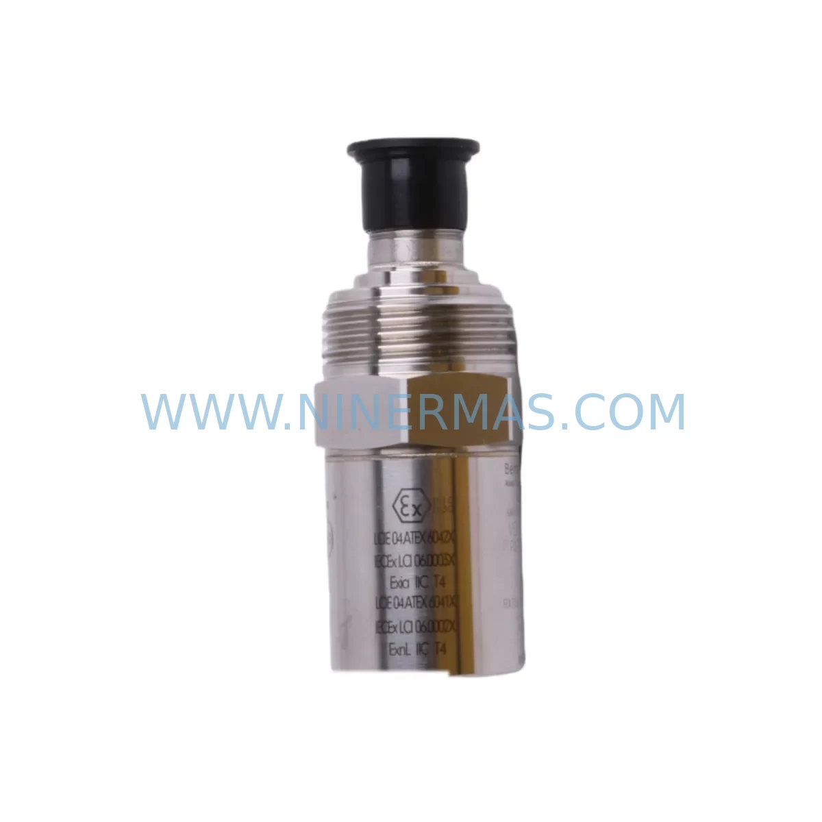
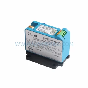
Bently Nevada 190501-12-00-00 Retrofit Velomitor CT Sensor
Verify the part, confirm the platform family, and move straight into quotation with the right commercial details.
RFQ Ready
- SKU190501-12-00-00
- CategoryTSI & Rotating Machinery Monitoring
- BrandBently Nevada
- SupportAvailability, lead time, condition, and shipping coordination
How Buyers Usually Use This Page
- Confirm the exact part number and platform family before sending the quote request.
- Use direct email when quantity, condition, and destination are already defined internally.
- Switch to the broader brand or category archive when you need alternates nearby.
Series Navigation
Move through the most common platform families behind this part.
Product RFQ
Send this part directly for quotation.
Include quantity, required condition, destination country, and target delivery timing. Current reference: Bently Nevada 190501-12-00-00 Retrofit Velomitor CT Sensor with SKU 190501-12-00-00.
Bently Nevada 190501-12-00-00 Retrofit Velomitor CT Sensor: Legacy-Compatible Vibration Monitoring Upgrade
The Bently Nevada 190501-12-00-00 is a Velomitor CT Series piezo-velocity vibration sensor widely deployed in rotating machinery protection and condition monitoring systems across oil and gas, power generation, petrochemical, and heavy industrial facilities. As legacy Bently Nevada monitoring architectures age and original spare parts become increasingly scarce, the 190501-12-00-00 remains one of the most sought-after retrofit-compatible components for engineers tasked with sustaining continuous plant operations without a full system overhaul.
NINERMAS maintains verified inventory of the 190501-12-00-00 to support planned maintenance shutdowns, emergency replacements, and phased system modernization programs. Each unit is subject to pre-shipment functional testing and ships with a 12-month warranty covering manufacturing defects and performance conformance.
Upgrade Compatibility Table
| Parameter | 190501-12-00-00 Specification | Retrofit / Replacement Notes |
|---|---|---|
| Sensor Type | Velomitor CT Piezo-Velocity | Direct replacement for earlier Velomitor and compatible velocity transducer variants |
| Output Signal | Voltage output (mV/mm/s or mV/in/s) | Verify input card scaling on 3500/42M Proximitor/Seismic Monitor or equivalent rack module |
| Connector / Cable Interface | 2-pin MIL-spec connector | Confirm existing field cable termination; adapter may be required for older armored cable assemblies |
| Mounting | Stud mount (standard industrial) | Check bearing housing thread size; re-tap if corroded; confirm torque spec before installation |
| Operating Temperature | -40°C to +121°C | Suitable for most turbine, compressor, and pump bearing housings in standard environments |
| Compatible Monitor Rack | Bently Nevada 3500 Series, 3300 Series | Confirm rack I/O card firmware revision; update if required for CT-series transducer recognition |
| Communication Protocol | Analog (hardwired to monitor rack) | No protocol migration required; signal feeds directly into 3500/42M or 3500/40M monitor cards |
| Installation Space | Compact body; standard industrial footprint | Verify clearance at bearing housing; no bracket modification typically required for like-for-like swap |
| Commissioning | Bias voltage check, sensitivity verification | Use Bently Nevada TK-3 or equivalent calibration tool; confirm alarm and trip setpoints post-installation |
| Warranty | 12-Month Warranty — covers manufacturing defects and performance conformance from shipment date | |
Retrofit Planning for Existing Automation Systems
Replacing the 190501-12-00-00 in an operating plant requires a structured approach that accounts for the broader monitoring architecture. In most installations, this sensor feeds vibration data into a Bently Nevada 3500 Series rack — typically via a 3500/42M Proximitor/Seismic Monitor card or a 3500/40M Proximitor Monitor module. Before pulling the old sensor, engineers should document the existing bias voltage reading, sensitivity factor entered in the monitor configuration, and the alarm/trip setpoints stored in the rack’s non-volatile memory.
In facilities running older Bently Nevada 3300 Series racks, the retrofit path may involve a parallel upgrade of the monitor card itself, since some 3300-era I/O modules do not natively support the CT-series output characteristics. In these cases, a 3500/42M card swap — or a full rack migration to the 3500 platform — is often planned concurrently with the sensor replacement to avoid a second shutdown cycle.
Field wiring is a critical checkpoint. The 190501-12-00-00 uses a standard 2-pin MIL-spec connector, but legacy installations may have armored cable assemblies terminated with older connector styles. Inspecting the junction box and confirming cable continuity before the shutdown window begins can prevent delays. If the existing cable run is damaged or undersized, a replacement Bently Nevada armored extension cable (such as those in the 330130 series) should be staged alongside the sensor.
For plants integrating vibration data into a System 1 condition monitoring platform or a third-party DCS via a 3500/92 Communication Gateway, the retrofit should include a post-installation data validation step to confirm that the new sensor’s signal is correctly mapped in the historian and that no channel offset has been introduced. Where the 3500 rack communicates over Modbus TCP or FOUNDATION Fieldbus to a plant DCS, the I/O address mapping for the replaced channel should be verified against the existing control narrative before returning the machine to service.
In multi-machine trains — such as gas turbine-compressor sets — the 190501-12-00-00 may be installed on both the driver and driven equipment. Coordinating a simultaneous replacement on all affected measurement points during a single outage window reduces total downtime exposure and avoids asymmetric monitoring gaps. Spare 3500/15 Power Supply modules and 3500/05 System Monitor cards should be on hand during the outage to address any rack-level faults discovered during the work scope.
Where the plant’s safety instrumented system (SIS) relies on vibration trip signals from the 3500 rack, the retrofit must be coordinated with the SIS engineer to ensure the trip channel is properly bypassed and reinstated in accordance with the site’s management of change (MOC) procedure. A 3500/33 16-Channel Relay Output module or equivalent relay card may need to be temporarily inhibited during sensor swap and re-enabled only after the new sensor’s bias and sensitivity have been confirmed within specification.
Downtime Control During System Migration
Minimizing unplanned downtime is the primary driver behind maintaining a reliable supply of the 190501-12-00-00. When a sensor fails in service, the machine protection system typically drives a trip or forces a manual shutdown to prevent bearing damage. Having a verified replacement unit on the shelf — rather than waiting on a spot-buy with uncertain lead times — is the single most effective downtime reduction measure available to maintenance teams.
For planned replacements, the recommended approach is to pre-stage the 190501-12-00-00 alongside all associated consumables: mounting stud, anti-seize compound, connector backshell, and cable tie-wraps. A pre-installation bench check — confirming the sensor’s open-circuit bias voltage and insulation resistance — takes less than ten minutes and eliminates the risk of installing a non-conforming unit. This step is especially important when drawing from long-term storage stock, where connector corrosion or seal degradation can affect performance.
During the swap, the original program logic in the 3500 rack does not require modification for a like-for-like sensor replacement. The monitor card retains its configuration — including full-scale range, alarm setpoints, and transducer type selection — across a power cycle, provided the rack’s battery-backed memory is functional. Verifying the 3500/05 System Monitor status before the outage confirms that configuration memory is intact and that no rack-level faults will complicate the restart sequence.
Post-installation, the commissioning sequence should include a slow-roll vibration check at reduced machine speed before returning to full load. This confirms that the new sensor is correctly oriented, properly torqued, and producing a clean signal free of electrical noise or mechanical resonance artifacts. Any HMI faceplate trends on the System 1 platform or DCS overview screen should be reviewed to confirm the channel is live and tracking expected vibration levels before the bypass is lifted and the machine is released to operations.
Retrofit Support FAQ
Q: Is the 190501-12-00-00 a direct drop-in replacement for earlier Velomitor models?
A: In most cases, yes. The Velomitor CT Series was designed to be backward-compatible with standard Velomitor mounting and wiring configurations. However, you should verify the sensitivity factor (mV/mm/s or mV/in/s) entered in your monitor card matches the 190501-12-00-00 specification sheet, and confirm that your rack firmware supports CT-series transducer recognition. If you are replacing a non-CT Velomitor variant, a monitor card configuration update may be required.
Q: What commissioning steps are required after installation?
A: After mechanical installation and cable connection, measure the sensor’s bias voltage at the monitor card input terminals — it should fall within the specified range for the 190501-12-00-00. Confirm the sensitivity factor in the monitor configuration, verify alarm and trip setpoints are correctly set, and perform a slow-roll check at reduced machine speed. If the installation feeds a System 1 historian or DCS, validate that the channel is correctly mapped and trending before releasing the machine to full operation.
Q: Can you confirm compatibility with the Bently Nevada 3500 and 3300 Series racks?
A: The 190501-12-00-00 is compatible with the Bently Nevada 3500 Series rack platform, including the 3500/42M Proximitor/Seismic Monitor card. Compatibility with 3300 Series racks depends on the specific monitor card variant and firmware revision installed. For 3300-era installations, we recommend confirming the monitor card’s transducer input specification before ordering. Our technical team can assist with compatibility verification based on your rack configuration.
Q: What does the 12-month warranty cover, and what is your typical lead time?
A: The 12-month warranty covers manufacturing defects and performance non-conformance from the date of shipment. Each unit undergoes pre-shipment functional testing before dispatch. For in-stock units, standard lead time is 3–7 business days for international shipments. Emergency orders can be accommodated — contact our team directly to confirm current stock availability and expedited shipping options.
| Product Series | 3500 series |
|---|---|
| Country of Origin | US |
Catalog Continuation
More Bently Nevada modules in the catalog.
Use the brand lane to compare nearby part numbers, platform-adjacent modules, and other inquiry-ready listings before sending your final RFQ.
SKU: 330194-13-20-10-00
Bently Nevada 330194-13-20-10-00 Safety-Reliable Monitor for Critical Control
SKU: 330701-00-40-10-11-05
Bently Nevada 330701-00-40-10-11-05 Safety Vibration Monitor
SKU: 21000-33-05-00-035-03-02
Bently Nevada 21000-33-05-00-035-03-02 Safety Relay
Catalog Continuation
Alternative parts within TSI & Rotating Machinery Monitoring.
Stay inside the same system family when you need substitutes, adjacent modules, or a broader shortlist for procurement review.