Original Industrial Spare Part
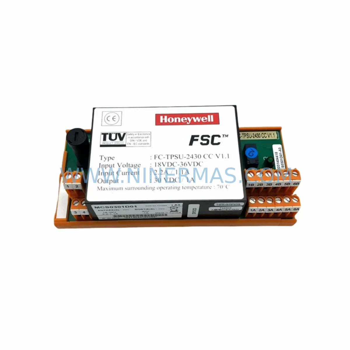
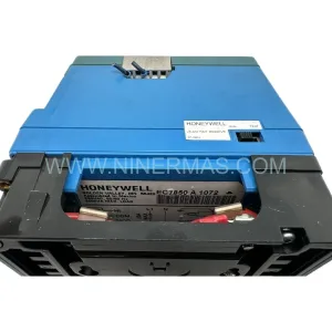
Honeywell FC-TPSU-2430 V1.1 Retrofit-Compatible Power Supply for Legacy Systems
Verify the part, confirm the platform family, and move straight into quotation with the right commercial details.
RFQ Ready
- SKUFC-TPSU-2430 V1.1
- CategorySIS Safety & Redundancy Systems
- BrandHoneywell
- SupportAvailability, lead time, condition, and shipping coordination
How Buyers Usually Use This Page
- Confirm the exact part number and platform family before sending the quote request.
- Use direct email when quantity, condition, and destination are already defined internally.
- Switch to the broader brand or category archive when you need alternates nearby.
Series Navigation
Move through the most common platform families behind this part.
Product RFQ
Send this part directly for quotation.
Include quantity, required condition, destination country, and target delivery timing. Current reference: Honeywell FC-TPSU-2430 V1.1 Retrofit-Compatible Power Supply for Legacy Systems with SKU FC-TPSU-2430 V1.1.
Honeywell FC-TPSU-2430 V1.1 Retrofit-Compatible Power Supply for Legacy Safety Manager Systems
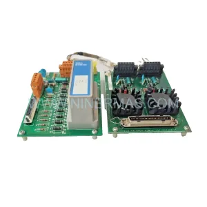
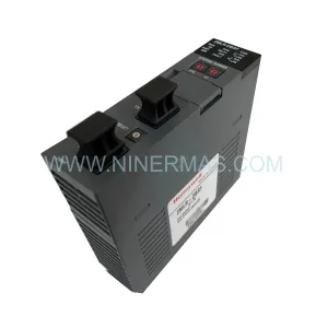
The Honeywell FC-TPSU-2430 V1.1 is a critical power supply module designed for the Safety Manager FC Series platform, widely deployed in process safety and emergency shutdown (ESD) systems across oil and gas, petrochemical, and power generation facilities. As legacy FC Series installations approach end-of-life or require capacity expansion, the FC-TPSU-2430 V1.1 serves as a direct retrofit-compatible replacement that preserves existing rack architecture, terminal wiring, and safety logic without requiring a full system overhaul.
This module delivers 24 VDC output at 30 A continuous load capacity, making it suitable for powering FC Series backplanes, I/O modules, and communication interfaces within the same control cabinet. Its form factor matches the original FC-TPSU-2430 footprint, allowing engineers to swap the unit into existing rack slots without mechanical modification. For sites running redundant power configurations, the FC-TPSU-2430 V1.1 supports parallel operation with a second power supply module, maintaining system availability during planned maintenance windows.
Upgrade Compatibility Table
| Parameter | FC-TPSU-2430 V1.1 (This Unit) | Notes / Retrofit Guidance |
|---|---|---|
| Output Voltage | 24 VDC | Matches FC Series backplane bus voltage; no regulator adjustment required |
| Output Current | 30 A continuous | Verify total I/O module load before installation; add second unit if load exceeds 28 A |
| Input Voltage Range | 85–264 VAC / 120–370 VDC | Wide-range input; compatible with both 110 VAC and 220 VAC site supplies |
| Rack Slot Compatibility | FC Series standard chassis | Direct drop-in; no chassis modification needed |
| Communication Interface | N/A (power module) | Does not affect FC-SDNM-01 or FC-SDNM-02 network module addressing |
| Redundancy Support | Yes (parallel operation) | Pair with second FC-TPSU-2430 for 1+1 redundant power; no additional configuration required |
| Installation Space | Standard FC chassis slot | Confirm slot availability in FC-RACK-0800 or FC-RACK-1600 chassis before ordering |
| Firmware / Programming | Not applicable | No firmware update required; safety logic in FC-CPU-0714 unaffected |
| Warranty | 12 Months | Covered from date of shipment; includes pre-shipment functional test documentation |
Retrofit Planning for Existing Automation Systems
Replacing a failed or aging power supply in a live Safety Manager FC Series installation requires careful pre-work to avoid unplanned shutdowns. Before removing the existing unit, engineers should audit the total power draw of all installed modules in the chassis. A typical FC Series rack may include the FC-CPU-0714 central processing unit, multiple FC-AI16-0800 analog input modules, FC-DO08-0800 digital output modules, and FC-DI16-0800 digital input modules. Each of these modules draws current from the 24 VDC bus, and the cumulative load must remain within the 30 A rating of the FC-TPSU-2430 V1.1.
For installations that have expanded I/O capacity over time — for example, by adding FC-AO08-0800 analog output modules or FC-SDO08-0800 supervised digital output modules — it is advisable to recalculate the power budget before committing to a single-supply configuration. If the calculated load approaches or exceeds 28 A, a second FC-TPSU-2430 V1.1 should be installed in the redundant power slot to provide load sharing and fault tolerance.
Terminal wiring for the AC input side of the FC-TPSU-2430 V1.1 uses standard screw-terminal connections. Engineers should photograph and label all existing wiring before disconnection, particularly the L, N, and PE terminals, as well as any remote inhibit or status signal wiring connected to the original unit. The output DC bus connects directly to the chassis backplane via the module’s edge connector — no separate DC wiring is required between the power supply and the backplane.
For sites where the FC Series system communicates with a DCS or SCADA platform via the FC-SDNM-01 Modbus TCP network module or the FC-SDNM-02 PROFIBUS DP interface, replacing the power supply does not affect network module addressing or communication parameters. However, it is good practice to notify the control room operator before initiating the swap, as the brief power interruption during module exchange may trigger a communication timeout alarm at the DCS workstation.
If the retrofit is part of a broader migration from the FC Series to a newer safety platform such as the Honeywell Safety Manager SC, the FC-TPSU-2430 V1.1 can continue to power the legacy FC rack during a phased cutover, allowing the new system to be commissioned and validated in parallel before the final switchover. This approach minimizes the risk of simultaneous changes to both the safety logic and the power infrastructure.
Downtime Control During System Migration
Minimizing downtime during a power supply replacement in a safety-critical system requires a structured approach. The recommended sequence begins with a pre-maintenance review of the current safety logic in the FC-CPU-0714, confirming that all cause-and-effect matrices and bypass states are documented and that the system is in a known, stable condition before work begins.
Where site procedures permit, the replacement should be performed during a scheduled maintenance window with the process unit in a safe state. If the FC Series rack supports hot-swap power supply replacement — which depends on whether a second FC-TPSU-2430 is installed in the redundant slot — the swap can be completed without de-energizing the chassis, preserving the safety logic execution and all I/O states throughout the procedure.
For single-supply configurations, a controlled shutdown sequence should be followed: inhibit all outputs via the FC-CPU-0714 operator interface, confirm that all field devices have reached a safe state, then de-energize the AC input to the power supply before removing the module. After installing the FC-TPSU-2430 V1.1, restore AC power and verify that the 24 VDC output is within specification before releasing the CPU from inhibit mode.
Post-installation verification should include a functional check of all I/O modules, confirmation that the FC-SDNM-01 or FC-SDNM-02 communication link has re-established, and a review of the system event log to confirm no unexpected alarms were generated during the power cycle. The entire procedure, from isolation to restoration, can typically be completed within 30 to 60 minutes for a well-prepared team, keeping unplanned process downtime to a minimum.
Each FC-TPSU-2430 V1.1 supplied by NINERMAS undergoes pre-shipment functional testing under load conditions, with test results documented and included with the shipment. This ensures that the replacement unit is verified operational before it reaches the site, reducing the risk of a second failure during the maintenance window.
Retrofit Support FAQ
Q1: Is the FC-TPSU-2430 V1.1 a direct replacement for the original FC-TPSU-2430?
Yes. The V1.1 revision maintains full mechanical and electrical compatibility with the original FC-TPSU-2430. It fits the same chassis slot, uses the same terminal connections, and delivers the same 24 VDC / 30 A output. No modifications to the chassis, backplane, or field wiring are required.
Q2: Can this unit be installed while the FC Series system is running?
Hot-swap installation is possible only if a second power supply is already installed in the redundant slot and carrying the full chassis load. In single-supply configurations, a controlled shutdown of the chassis is required before replacing the module. Always follow your site’s safety management of change (MOC) procedure before performing any maintenance on a live safety system.
Q3: What pre-shipment testing is performed on this unit?
Each FC-TPSU-2430 V1.1 is tested under rated load conditions prior to shipment. Output voltage regulation, current limiting, and input range performance are verified. A test report is included with each unit. The module is covered by a 12-month warranty from the date of shipment.
Q4: How quickly can this unit be shipped, and is stock available?
NINERMAS maintains ready stock of the FC-TPSU-2430 V1.1 to support urgent retrofit and breakdown replacement requirements. Standard lead time is 3–7 business days for international shipments. For urgent requirements, expedited shipping options are available. Contact sale@ninermas.com or +0086 187 5021 5667 to confirm current stock availability and delivery schedule.
| Product Series | Safety Manager |
|---|---|
| Country of Origin | US |
Catalog Continuation
More Honeywell modules in the catalog.
Use the brand lane to compare nearby part numbers, platform-adjacent modules, and other inquiry-ready listings before sending your final RFQ.
Catalog Continuation
Alternative parts within SIS Safety & Redundancy Systems.
Stay inside the same system family when you need substitutes, adjacent modules, or a broader shortlist for procurement review.