Original Industrial Spare Part
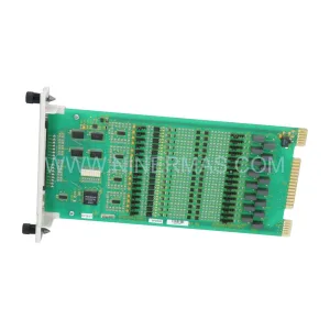
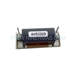
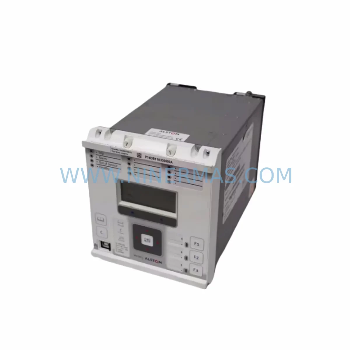
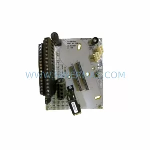
Alstom P14DB11A330500A Retrofit-Compatible Relay Legacy Systems
Verify the part, confirm the platform family, and move straight into quotation with the right commercial details.
RFQ Ready
- SKUP14DB11A330500A
- CategorySIS Safety & Redundancy Systems
- BrandALSTOM
- SupportAvailability, lead time, condition, and shipping coordination
How Buyers Usually Use This Page
- Confirm the exact part number and platform family before sending the quote request.
- Use direct email when quantity, condition, and destination are already defined internally.
- Switch to the broader brand or category archive when you need alternates nearby.
Series Navigation
Move through the most common platform families behind this part.
Product RFQ
Send this part directly for quotation.
Include quantity, required condition, destination country, and target delivery timing. Current reference: Alstom P14DB11A330500A Retrofit-Compatible Relay Legacy Systems with SKU P14DB11A330500A.
Alstom P14DB11A330500A Retrofit-Compatible Protection Relay: Seamless Legacy System Modernization
The Alstom P14DB11A330500A is a distance protection relay from Alstom’s established P14 series, widely deployed across transmission substations, industrial power distribution panels, and legacy control cabinets throughout the 1990s and 2000s. As original equipment reaches end-of-life and OEM support is discontinued, plant engineers and maintenance teams face the critical challenge of sourcing verified replacement units that maintain full backward compatibility with existing wiring, backplane interfaces, and SCADA communication links. NINERMAS supplies the P14DB11A330500A as a tested, retrofit-ready spare with a 12-month warranty, enabling direct drop-in replacement without requiring panel redesign or software re-engineering.
Whether you are managing a scheduled overhaul, responding to an unexpected relay failure, or executing a phased modernization of aging protection infrastructure, the P14DB11A330500A provides a reliable bridge between legacy system architecture and current operational demands. This page covers everything your engineering team needs to plan and execute a successful retrofit: terminal wiring compatibility, backplane interface verification, communication protocol migration, installation space confirmation, and on-site commissioning procedures.
Upgrade Compatibility Table
| Parameter | P14DB11A330500A (This Unit) | Notes / Retrofit Guidance |
|---|---|---|
| Interface Type | P14 Series Backplane Connector | Direct pin-compatible with standard P14 rack; verify rack revision before installation |
| Installation Requirement | 19″ rack-mount, standard P14 chassis slot | Confirm available slot depth and adjacent module clearance; no panel cutout modification required |
| Communication Compatibility | IEC 60870-5-103 / RS-485 Kbus | Compatible with existing Kbus wiring; confirm baud rate and address settings match legacy configuration |
| Replacement Recommendation | Direct replacement for P14DB11A330500A; cross-reference P14DB11A330400A for adjacent zone coverage | Verify protection zone settings and CT/VT ratios before energizing |
| Commissioning Focus | Zone reach settings, time-delay coordination, binary I/O mapping, HMI display verification | Use original relay test records as baseline; re-run secondary injection tests after installation |
| 12-Month Warranty | Yes — all units tested before shipment | Warranty covers manufacturing defects; includes pre-shipment functional test report on request |
Retrofit Planning for Existing Automation Systems
A successful P14DB11A330500A retrofit begins well before the unit arrives on site. Engineering teams should pull the original relay settings file and protection coordination study to establish a verified baseline. The P14 series uses a modular rack architecture, and the P14DB11A330500A occupies a standard slot within the P14 chassis backplane. Before removal of the failed or end-of-life unit, photograph all terminal wiring, label each conductor, and record the existing module address configured via the front-panel DIP switches or keypad menu.
Power supply capacity is a frequent oversight in relay retrofit projects. The P14 rack power supply module — typically a 48 VDC or 110 VDC input unit depending on substation battery configuration — must be verified to support the full load of all installed modules after the replacement. If the existing power supply is also approaching end-of-life, sourcing a replacement P14 power supply unit in parallel with the P14DB11A330500A avoids a secondary unplanned outage.
Terminal wiring on the P14DB11A330500A follows the standard P14 series rear terminal block layout. Current transformer (CT) and voltage transformer (VT) secondary circuits must be shorted and isolated before the old relay is withdrawn from the rack. The replacement unit should be inserted with all binary input and output wiring disconnected initially, allowing the engineer to verify power-up, self-test completion, and settings upload before reconnecting trip and alarm circuits.
Communication link restoration is critical in substations using IEC 60870-5-103 over RS-485 Kbus. The P14DB11A330500A must be assigned the same Kbus address as the unit it replaces. If the substation RTU or SCADA front-end is a legacy Alstom MVAX31 or similar concentrator, confirm that the data model mapping in the RTU configuration matches the relay’s IEC 103 information object addresses. Mismatched addresses will cause silent data loss on the SCADA display without triggering an obvious alarm.
For sites migrating from older P14 variants such as the P14NB11A3B0500A or earlier numeric relay generations, the retrofit may also involve updating the HMI mimic panel. If the control room uses a dedicated relay HMI or a DCS faceplate tied to the relay’s binary outputs, verify that the output relay contact assignments (trip, alarm, start, CB fail) match the new unit’s default configuration. Reprogramming output matrix settings is straightforward via the relay’s front-panel menu but must be completed and verified before the protection is returned to service.
Sites with I/O expansion requirements should evaluate whether the existing P14 rack has available slots for additional I/O modules. In multi-feeder protection panels, it is common to find the P14DB11A330500A installed alongside MiCOM P120, MiCOM P121, or MiCOM P122 overcurrent and earth fault relays sharing the same control cabinet. Coordination between these devices — particularly time-grading and intertripping logic — must be re-verified after any relay replacement to ensure the protection discrimination scheme remains intact.
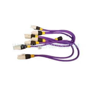
Programming cable availability is another practical consideration. The P14 series uses a dedicated front-port programming cable for settings upload via Alstom’s relay setting software. Confirm the cable and a compatible laptop with the correct software version are available on site before the maintenance window begins. Uploading a pre-verified settings file reduces commissioning time significantly and minimizes the risk of manual entry errors under time pressure.
Downtime Control During System Migration
Minimizing outage duration during a P14DB11A330500A replacement requires disciplined pre-work and a clearly sequenced switching program. The recommended approach is to complete all preparatory steps — settings file preparation, terminal labeling, spare unit testing, and communication address verification — during normal operations, so that the actual relay swap can be executed within a single planned maintenance window.
Before the outage window opens, the replacement P14DB11A330500A should be bench-tested with the target settings file loaded and verified. This includes confirming that all binary inputs respond correctly to test signals, that output relays operate at the correct thresholds, and that the Kbus communication link is established with a test RTU or laptop running the appropriate IEC 103 master software. A pre-shipment test report from NINERMAS provides the baseline functional verification; site acceptance testing confirms settings-specific behavior.
During the outage, the switching sequence should isolate the protected feeder, open the circuit breaker, and apply earthing before any work on the relay panel. The old P14DB11A330500A is withdrawn, the replacement inserted, wiring reconnected in reverse order of removal, and the communication link re-established. A secondary injection test — even a simplified one covering trip function and timing — should be completed before the feeder is returned to service. This protects the original program logic and ensures the protection scheme is fully functional before the maintenance window closes.
For sites where extended outages are not acceptable, a temporary bypass protection arrangement using a portable relay test set can maintain basic overcurrent protection on the feeder while the permanent relay is replaced. This approach requires coordination with the system operator and should be documented in the switching program.
Retrofit Support FAQ
Q1: Is the P14DB11A330500A a direct replacement for the unit currently installed in my P14 rack?
A: Yes, provided your existing installation uses the standard P14 series backplane and the same protection function variant. Verify the full model number on the nameplate of the unit being replaced. If the last digits differ (e.g., P14DB11A330400A vs. P14DB11A330500A), the units may have different protection reach or I/O configurations. Contact NINERMAS with your nameplate details for cross-reference confirmation before ordering.
Q2: What commissioning steps are required after installation?
A: At minimum, upload the verified settings file, confirm Kbus address assignment, perform a secondary injection test covering the main protection function (distance zone trip and timing), verify all binary output contacts, and confirm SCADA data visibility from the RTU. For sites with intertripping or busbar protection schemes, additional scheme testing is required before returning the feeder to service.
Q3: How is the unit tested before shipment, and what documentation is provided?
A: All P14DB11A330500A units supplied by NINERMAS undergo a pre-shipment functional test covering power-up self-test, output relay operation, and communication port verification. A test report is available on request. The 12-month warranty covers manufacturing defects from the date of shipment and applies to all units in our inventory.
Q4: What is the typical lead time, and do you hold stock?
A: NINERMAS maintains inventory of P14 series components to support urgent maintenance requirements. Standard lead time for in-stock units is 3–7 business days for international shipment. For large-quantity orders or long-term spare parts supply agreements covering multiple P14 variants, contact our sales team to discuss stocking arrangements and volume pricing.
| Product Series | Other series |
|---|
Catalog Continuation
More ALSTOM modules in the catalog.
Use the brand lane to compare nearby part numbers, platform-adjacent modules, and other inquiry-ready listings before sending your final RFQ.
Catalog Continuation
Alternative parts within SIS Safety & Redundancy Systems.
Stay inside the same system family when you need substitutes, adjacent modules, or a broader shortlist for procurement review.
SKU: KFD2-STC4-EX1.20
Pepperl+Fuchs KFD2-STC4-EX1.20 Service-Ready Spare Part
SKU: power supply module
GE Multilin UR RHH Safety-Reliable Power Supply for Critical Control
SKU: 8C-PCNT02 8C-PCNT01
Honeywell 8C-PCNT02 Safety-Reliable Controller Critical Sites