Original Industrial Spare Part
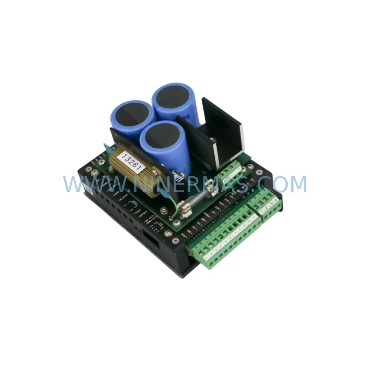
PMI KXA-48-8-16 Service-Ready Spare Part for Industrial Maintenance
Verify the part, confirm the platform family, and move straight into quotation with the right commercial details.
RFQ Ready
- SKUKXA-48-8-16 PS/AUX/PS 0088060-004 PH265-02 MDVHX30ITC02 7KG7500-0AA02-0AA0/CC
- CategoryPLC & Industrial Automation Modules
- BrandPMI
- SupportAvailability, lead time, condition, and shipping coordination
How Buyers Usually Use This Page
- Confirm the exact part number and platform family before sending the quote request.
- Use direct email when quantity, condition, and destination are already defined internally.
- Switch to the broader brand or category archive when you need alternates nearby.
Series Navigation
Move through the most common platform families behind this part.
Product RFQ
Send this part directly for quotation.
Include quantity, required condition, destination country, and target delivery timing. Current reference: PMI KXA-48-8-16 Service-Ready Spare Part for Industrial Maintenance with SKU KXA-48-8-16 PS/AUX/PS 0088060-004 PH265-02 MDVHX30ITC02 7KG7500-0AA02-0AA0/CC.
PMI KXA-48-8-16 Service-Ready Spare Part for Industrial Maintenance
The PMI KXA-48-8-16 is a ruggedized PWM servo amplifier engineered for demanding industrial environments where motion control reliability is non-negotiable. As a service-ready spare part, the KXA-48-8-16 is stocked, pre-tested, and available for immediate dispatch to support emergency replacement, scheduled maintenance, and long-term spare parts inventory programs. Unplanned servo drive failures are among the leading causes of extended production downtime in automated manufacturing, energy, and process control facilities. Maintaining a verified spare of the KXA-48-8-16 in your maintenance inventory directly reduces mean time to repair (MTTR) and protects critical production continuity.
The KXA-48-8-16 operates on a 48 VDC bus and delivers 8 A continuous output current with a 16 A peak rating, making it well-suited for high-dynamic servo axes in machine tools, robotics, semiconductor handling, and precision positioning systems. Its PWM switching architecture provides smooth torque control across the full speed range, while the ruggedized design addresses vibration, thermal cycling, and EMI exposure common in industrial cabinet environments. Each unit supplied by NINERMAS undergoes pre-shipment functional verification and is backed by a 12-month warranty from the date of delivery.
Spare Maintenance Table
| Parameter | Specification |
|---|---|
| SKU / Part Number | KXA-48-8-16 |
| Brand / Manufacturer | PMI Motion Technologies |
| Series | KXA Series |
| Drive Type | PWM Servo Amplifier |
| DC Bus Input Voltage | 48 VDC |
| Continuous Output Current | 8 A |
| Peak Output Current | 16 A |
| Feedback Interface | Incremental Encoder |
| Control Mode | Torque / Velocity |
| Mounting Style | Panel / DIN Rail Compatible |
| Operating Temperature | 0°C to +50°C |
| Protection Class | IP20 (cabinet-mounted) |
| Application Environment | Industrial Automation, Robotics, Semiconductor, Machine Tool |
| Compatibility | PMI KXA Series, U-Series Servo Motors, Encoder Feedback Systems |
| Pre-Shipment Testing | Yes — functional verification included |
| Warranty | 12 Months from Date of Delivery |
| Supply Condition | Original Spare, Service-Ready |
Maintenance Planning for Continuous Operation
Effective maintenance planning for a servo drive system extends well beyond the amplifier itself. When replacing the KXA-48-8-16, maintenance engineers should conduct a systematic inspection of all interconnected components within the same electrical circuit and control cabinet to prevent repeat failures and ensure full system restoration.
Begin with the DC bus power supply feeding the KXA-48-8-16. Verify that the bus voltage is stable at 48 VDC under load and that the power supply module — such as a PMI-compatible regulated DC supply or equivalent industrial DIN rail power supply — shows no signs of ripple, thermal stress, or capacitor degradation. A failing power supply is a common root cause of servo amplifier damage and should be replaced proactively when the drive is swapped.
Inspect the encoder feedback cable connecting the servo motor to the KXA-48-8-16. Shielded encoder cables are susceptible to insulation breakdown, connector pin corrosion, and shield continuity loss, particularly in high-cycle or high-vibration environments. Replacing the feedback cable alongside the amplifier eliminates a frequent source of intermittent faults after drive replacement. Similarly, check the motor power cable for insulation integrity and secure termination at both the amplifier output and the motor terminal box.
For systems using PMI U-series servo motors — such as the U9M4H or U12M4H — verify that the motor winding resistance and insulation resistance are within specification before reconnecting to the new KXA-48-8-16. A degraded motor winding can immediately stress a replacement amplifier and shorten its service life. If the motor has accumulated significant operating hours, scheduling a motor inspection or replacement as part of the same maintenance window is a sound investment.
Within the control cabinet, inspect the DC bus fuse or circuit breaker protecting the KXA-48-8-16 supply rail. Fuses that have experienced overcurrent events may show signs of thermal discoloration or weakened element integrity even if they have not blown. Replace suspect fuses with correctly rated components. Terminal blocks and DIN rail mounting hardware should be checked for secure torque and absence of oxidation on copper conductors.
If the KXA-48-8-16 interfaces with a PLC or motion controller via an analog command signal or digital enable line, verify the signal integrity at the amplifier input connector. Inspect the command signal cable, shielding, and grounding. For systems using a dedicated motion controller or DSP-based command generator, confirm that the controller output is within the amplifier’s input voltage range and that no ground loops exist between the controller chassis and the amplifier chassis.
Regenerative resistors or braking resistors connected to the KXA-48-8-16 bus should be inspected for resistance value drift and thermal damage. An out-of-tolerance regenerative resistor can cause bus overvoltage faults during deceleration, leading to nuisance trips or amplifier damage. Companion amplifier models such as the KXA-48-8-8 (8 A continuous, 8 A peak) and the KXA-24-8-16 (24 VDC bus variant) share similar peripheral requirements and should be maintained under the same inspection protocol when present in the same cabinet or machine.
Signal isolation modules between the PLC I/O and the amplifier enable/fault circuits should be tested for correct output levels and response time. Degraded optocouplers or relay output modules can cause erratic enable behavior that mimics amplifier faults. Including a spare signal isolator in the maintenance kit alongside the KXA-48-8-16 spare is a practical risk mitigation measure for facilities with long procurement lead times.
Site Replacement Workflow
Before beginning the replacement of the KXA-48-8-16, isolate the machine from all energy sources following your site lockout/tagout (LOTO) procedure. Discharge the DC bus capacitors and verify zero voltage at the amplifier power terminals using a calibrated meter before touching any wiring.
Document the existing wiring configuration with photographs or a wiring diagram before disconnecting any cables. Note the positions of all connector plugs, the encoder cable routing, and the motor power cable dressing. This documentation is essential for accurate reconnection and reduces the risk of wiring errors that can damage the replacement unit.
Remove the failed KXA-48-8-16 from its mounting position. Inspect the mounting surface and adjacent components for signs of thermal damage, arcing, or contamination. Clean the mounting area before installing the replacement unit. Mount the new KXA-48-8-16 securely and reconnect all cables in the documented sequence, verifying connector seating and locking mechanisms.
Before applying power, perform a continuity check on the motor power cables and verify that the encoder cable shield is correctly terminated at the amplifier chassis ground. Apply control power first and confirm that the amplifier initializes without fault codes. Then apply DC bus power and verify bus voltage at the amplifier terminals. Command a low-speed jog motion to confirm encoder feedback direction and motor rotation direction before returning the axis to automatic operation.
Update your maintenance log with the replacement date, the serial number of the installed unit, and the pre-shipment test certificate reference. Schedule a follow-up inspection at 500 operating hours or 3 months, whichever comes first, to verify thermal performance and connector integrity of the new installation.
Spare Parts Support FAQ
Q1: Is the KXA-48-8-16 supplied by NINERMAS an original PMI spare part?
Yes. NINERMAS supplies original PMI KXA-48-8-16 servo amplifiers sourced through verified industrial channels. Each unit is functionally tested prior to shipment and is accompanied by a 12-month warranty covering defects in materials and workmanship under normal operating conditions.
Q2: What is the recommended spare parts inventory strategy for the KXA-48-8-16?
For facilities operating multiple axes using the KXA-48-8-16, maintaining a minimum of one spare unit per five installed drives is a widely adopted practice in industrial maintenance programs. For critical single-axis applications where downtime cost is high, a one-to-one spare ratio is recommended. NINERMAS offers reserved inventory programs that allow customers to commit to a quantity at a fixed price with staged delivery, protecting against lead time risk and price escalation.
Q3: How do I verify compatibility between the KXA-48-8-16 and my existing servo motor and controller?
Compatibility verification requires confirming three parameters: the DC bus voltage (48 VDC), the motor continuous and peak current requirements (must be within 8 A / 16 A), and the encoder feedback type (incremental encoder with compatible line count and connector pinout). NINERMAS technical support can assist with compatibility review based on your motor nameplate data and controller specifications before order placement.
Q4: What does the 12-month warranty cover, and what is the process for a warranty claim?
The 12-month warranty covers manufacturing defects and functional failures under normal operating conditions. It does not cover damage resulting from incorrect installation, overvoltage events, contamination, or unauthorized modification. To initiate a warranty claim, contact NINERMAS with the unit serial number, purchase order reference, and a description of the failure symptom. NINERMAS will arrange return shipping and provide a replacement or repaired unit within the agreed service lead time.
| Product Series | Other series |
|---|
Catalog Continuation
Alternative parts within PLC & Industrial Automation Modules.
Stay inside the same system family when you need substitutes, adjacent modules, or a broader shortlist for procurement review.
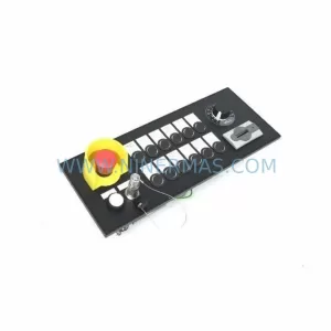
SKU: MPP1500D 6FC5303-1AF30-0AA0
Siemens MPP1500D 6FC5303-1AF30-0AA0 Retrofit Operator Panel
SKU: 6SL3224-0BE31-5UA0
Siemens 6SL3224-0BE31-5UA0 Service-Ready Spare Part