Original Industrial Spare Part
PERSKE KNS 51.14-2D Service-Ready Spare Part for Industrial Maintenance
Verify the part, confirm the platform family, and move straight into quotation with the right commercial details.
RFQ Ready
- SKUKNS 51.14-2D
- CategoryPLC & Industrial Automation Modules
- BrandPERSKE
- SupportAvailability, lead time, condition, and shipping coordination
How Buyers Usually Use This Page
- Confirm the exact part number and platform family before sending the quote request.
- Use direct email when quantity, condition, and destination are already defined internally.
- Switch to the broader brand or category archive when you need alternates nearby.
Series Navigation
Move through the most common platform families behind this part.
Product RFQ
Send this part directly for quotation.
Include quantity, required condition, destination country, and target delivery timing. Current reference: PERSKE KNS 51.14-2D Service-Ready Spare Part for Industrial Maintenance with SKU KNS 51.14-2D.
PERSKE KNS 51.14-2D Service-Ready Spare Part for Industrial Maintenance
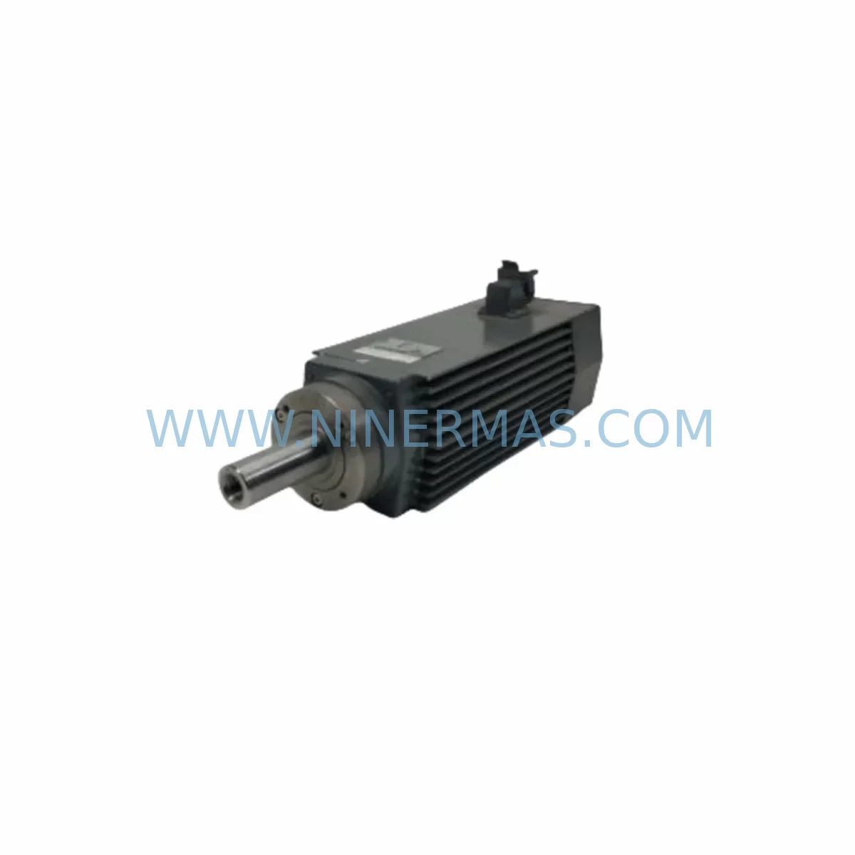
The PERSKE KNS 51.14-2D is a high-frequency CNC spindle motor widely deployed in woodworking machining centres, panel processing lines, and multi-axis routing systems. As legacy CNC installations continue operating well beyond their original design life, maintaining a verified, service-ready spare for the KNS 51.14-2D is one of the most effective strategies for controlling unplanned downtime risk. NINERMAS supplies original and OEM-equivalent KNS 51.14-2D units that have been inspected, function-tested, and prepared for immediate field installation — backed by a 12-month warranty and long-term supply commitment.
Spindle motor failure is among the highest-impact fault events in CNC production environments. A single unplanned spindle outage can halt an entire machining cell for hours or days while a replacement is sourced. Maintenance engineers who pre-position a KNS 51.14-2D spare in their local inventory eliminate this sourcing delay entirely, reducing mean time to repair (MTTR) to the time required for a physical swap and re-commissioning — typically under four hours for a trained technician.
The KNS 51.14-2D operates within the PERSKE KNS series architecture, sharing mechanical and electrical interface standards with adjacent models in the same family. This commonality simplifies spare parts planning: a single procurement decision covers a range of compatible machine configurations, reducing the total number of unique line items in your maintenance inventory while maximising coverage across your installed base.
Spare Maintenance Table
| SKU | KNS 51.14-2D |
| Brand | PERSKE |
| Series | KNS |
| Product Type | High-Frequency CNC Spindle Motor |
| Typical Application | CNC woodworking centres, panel routing, multi-axis machining |
| Cooling Method | Air-cooled (integrated fan) |
| Mounting Interface | KNS series standard flange — direct drop-in replacement |
| Electrical Interface | Compatible with KNS series VFD/inverter drive wiring harness |
| Origin | Germany (DE) |
| Compatibility | PERSKE KNS series CNC spindle assemblies; verify nameplate voltage and frequency before installation |
| Condition | Original spare / OEM-equivalent; function-tested prior to dispatch |
| Warranty | 12 Months from date of shipment |
| Lead Time | Subject to stock availability; contact for current lead time |
| Shipping | Global export; ESD-safe and vibration-protected packaging |
| Maintenance Recommendation | Inspect bearing condition, winding insulation resistance, and cooling fan integrity at each scheduled PM interval |
Maintenance Planning for Continuous Operation
Replacing a KNS 51.14-2D in the field is rarely an isolated task. A spindle motor fault is frequently a symptom of broader electrical or mechanical stress in the surrounding system, and a thorough site replacement should include inspection of all components that share the same power and signal circuit.
Begin with the VFD/inverter drive that powers the spindle. PERSKE KNS series spindles are typically driven by a compatible frequency inverter — check the drive’s output voltage, frequency range, and current rating against the KNS 51.14-2D nameplate data before energising the replacement unit. A drive that has been operating in a degraded state may have contributed to the original motor failure; replacing the spindle without inspecting the drive risks repeating the fault within weeks.
Inspect the spindle power cable and motor connector for insulation breakdown, pin corrosion, or mechanical damage at the cable entry point. High-cycle CNC environments subject these cables to continuous flexing, and a compromised cable can introduce intermittent faults that are difficult to diagnose after the new spindle is installed. Replace the cable assembly if any doubt exists about its condition.
Check the 24 VDC control power supply that feeds the machine’s I/O logic. Voltage sag or ripple on the control rail can cause spurious spindle enable/disable signals, leading to premature motor stress. A DIN-rail mounted industrial power supply with adequate current headroom is the correct replacement if the existing unit shows signs of ageing.
Review the I/O module responsible for spindle start, stop, and speed reference signals. On machines using a PLC-based controller, verify that the analogue output channel providing the speed reference to the VFD is within calibration. A drifting analogue output can cause the spindle to run at incorrect speeds, increasing mechanical wear on the new motor.
Inspect relay and contactor assemblies in the spindle control circuit. Contactors that have accumulated significant switching cycles may exhibit contact bounce or welding, both of which can damage the VFD input stage or the motor windings. Replace any contactor showing visible arc erosion on the contact faces.
Examine the terminal blocks and DIN-rail wiring in the control cabinet. Loose or corroded terminals in the spindle circuit are a common source of intermittent faults that are misdiagnosed as motor failures. Re-torque all terminals in the affected circuit and apply contact protection spray where appropriate.
If the machine uses a communication module (PROFIBUS, PROFINET, or CANopen) to coordinate spindle operation with the broader production line, verify that the module’s firmware is current and that the network topology has not been disrupted by the fault event. A communication timeout during spindle operation can trigger emergency stops that mask the underlying electrical fault.
For machines equipped with a signal isolator or analogue signal conditioner between the PLC and the VFD, verify isolation integrity and output linearity. Degraded isolation can introduce ground loops that corrupt the speed reference signal and cause erratic spindle behaviour after the replacement motor is installed.
Finally, inspect the HMI panel and operator interface for any latched fault codes or alarm history that may indicate recurring spindle overcurrent, overtemperature, or earth fault events prior to the failure. This historical data is invaluable for root-cause analysis and should be documented before the fault log is cleared during recommissioning.
Site Replacement Workflow
Step 1 — Isolate and lock out. De-energise the machine at the main isolator and apply LOTO (lockout/tagout) before opening the control cabinet or accessing the spindle assembly. Verify zero energy state with a calibrated voltage tester.
Step 2 — Document the existing installation. Photograph the spindle motor nameplate, cable routing, connector orientation, and any visible wear indicators before disassembly. This documentation supports accurate recommissioning and provides a baseline for future maintenance records.
Step 3 — Remove the failed unit. Disconnect the power cable and any sensor connectors (thermal protection, encoder, or speed feedback if fitted). Remove the spindle from its mounting flange, noting the torque specification for the retaining fasteners.
Step 4 — Inspect the mounting interface. Check the spindle housing bore and flange face for damage, contamination, or fretting corrosion. Clean and inspect the tool holder interface if the spindle incorporates an integrated tool clamping system.
Step 5 — Install the KNS 51.14-2D replacement. Mount the new unit to the specified torque, reconnect all cables in the correct orientation, and verify that the cooling air path is unobstructed. Do not energise the unit until all mechanical and electrical connections have been verified.
Step 6 — Commission and test. Restore power and run the spindle at low speed (10–20% of rated speed) for a minimum of five minutes before advancing to full operating speed. Monitor VFD output current, motor temperature, and vibration levels during the run-in period. Document the commissioning results and update the machine’s maintenance record.
This structured workflow minimises the risk of repeat failures, reduces total downtime, and ensures that the replacement KNS 51.14-2D is installed in a system that is ready to support reliable long-term operation.
Spare Parts Support FAQ
Q1: Is the KNS 51.14-2D still available as a new original spare, and what is the expected supply horizon?
A: NINERMAS maintains stock of original and OEM-equivalent KNS 51.14-2D units and actively monitors supply chain availability for PERSKE KNS series components. For end-of-life or discontinued models, we source from authorised distribution channels and verified surplus inventories. Contact our team for current stock status and long-term supply commitment options for your maintenance programme.
Q2: How is the KNS 51.14-2D tested before shipment?
A: Every unit dispatched by NINERMAS undergoes a pre-shipment function test that includes winding insulation resistance measurement, no-load run test, and visual inspection of the mechanical interface and connector condition. Units that do not meet acceptance criteria are quarantined and not dispatched. A test report is available on request.
Q3: Can the KNS 51.14-2D be used as a direct replacement for adjacent KNS series models?
A: The KNS 51.14-2D shares the standard KNS series mechanical interface, but electrical parameters (voltage, frequency, power rating) must be verified against the machine’s VFD configuration and the original motor nameplate before installation. NINERMAS technical support can assist with compatibility verification if you provide the machine model, existing motor nameplate data, and VFD type.
Q4: What does the 12-month warranty cover, and what is the claims process?
A: The 12-month warranty covers manufacturing defects and premature failure under normal operating conditions from the date of shipment. It does not cover damage resulting from incorrect installation, operation outside rated parameters, or physical mishandling. To initiate a warranty claim, contact NINERMAS with the original order reference, a description of the fault, and photographic evidence of the installation. Our team will advise on return logistics and replacement lead time.
| Product Series | Other series |
|---|
Catalog Continuation
Alternative parts within PLC & Industrial Automation Modules.
Stay inside the same system family when you need substitutes, adjacent modules, or a broader shortlist for procurement review.
SKU: MPP1500D 6FC5303-1AF30-0AA0
Siemens MPP1500D 6FC5303-1AF30-0AA0 Retrofit Operator Panel
SKU: 6SL3224-0BE31-5UA0
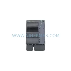
Siemens 6SL3224-0BE31-5UA0 Service-Ready Spare Part