Original Industrial Spare Part
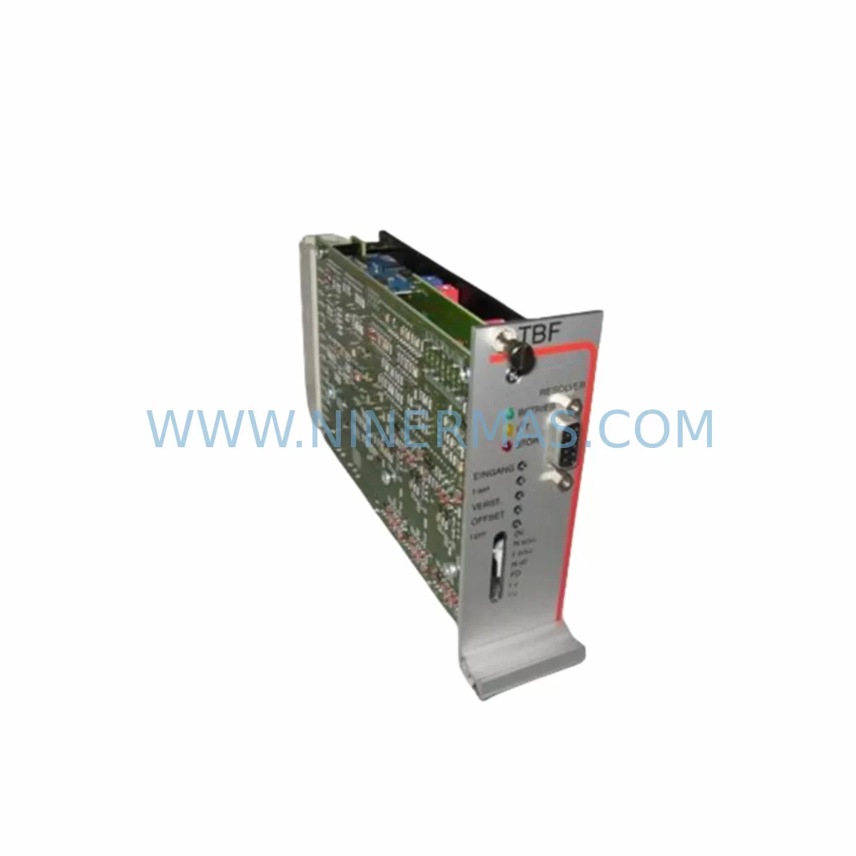
Parker TBF60/5R Retrofit-Compatible Servo Drive for Legacy Systems
Verify the part, confirm the platform family, and move straight into quotation with the right commercial details.
RFQ Ready
- SKUTBF60/5R 60V/5-15A
- CategoryPLC & Industrial Automation Modules
- BrandParker
- SupportAvailability, lead time, condition, and shipping coordination
How Buyers Usually Use This Page
- Confirm the exact part number and platform family before sending the quote request.
- Use direct email when quantity, condition, and destination are already defined internally.
- Switch to the broader brand or category archive when you need alternates nearby.
Series Navigation
Move through the most common platform families behind this part.
Product RFQ
Send this part directly for quotation.
Include quantity, required condition, destination country, and target delivery timing. Current reference: Parker TBF60/5R Retrofit-Compatible Servo Drive for Legacy Systems with SKU TBF60/5R 60V/5-15A.
Parker TBF60/5R Retrofit-Compatible Servo Drive for Legacy Systems
The Parker TBF60/5R is a 60V, 5–15A servo drive module from Parker’s TBF Series, widely deployed in legacy motion control systems across precision manufacturing, packaging lines, semiconductor handling, and industrial robotics. As original OEM supply channels for this model have been discontinued or constrained, the TBF60/5R has become a critical retrofit and spare parts target for maintenance engineers managing aging automation infrastructure.
NINERMAS supplies the Parker TBF60/5R as a retrofit-compatible replacement unit, fully pre-shipment tested and backed by a 12-month warranty. Each unit is verified against original Parker TBF Series electrical specifications before dispatch, ensuring that your replacement integrates cleanly into existing control cabinets without requiring redesign of surrounding circuitry.
For facilities running Parker motion controllers such as the Parker Compax3 or legacy ACR Series motion controllers, the TBF60/5R fits directly into established servo loops. Engineers replacing failed drives in multi-axis systems should confirm the axis address configuration and encoder feedback wiring before installation, as the TBF Series uses incremental encoder interfaces that must be matched to the host controller’s axis mapping. Where the original drive was paired with a Parker SSD 690+ series or similar variable-speed platform in a coordinated motion application, verify that the replacement drive’s current loop tuning parameters are re-entered from the original commissioning records.
Upgrade Compatibility Table
| Parameter | Parker TBF60/5R (This Unit) | Retrofit Notes |
|---|---|---|
| Supply Voltage | 60 VDC | Confirm DC bus rail voltage at cabinet; do not exceed rated input |
| Output Current Range | 5–15 A continuous | Match to motor nameplate peak current; verify thermal derating at ambient >40°C |
| Feedback Interface | Incremental Encoder (TTL) | Confirm encoder line count and differential signal integrity on existing cable |
| Communication / Control | Analogue ±10V / Step-Direction | Verify host controller output type; re-tune velocity and current loops after swap |
| Mounting / Form Factor | Panel-mount module | Confirm DIN rail or chassis mounting footprint matches existing cutout |
| Terminal Wiring | Screw-terminal block | Label and photograph all wiring before removal; re-torque terminals to spec |
| Backplane / Rack Interface | Standalone (no backplane bus) | No rack address configuration required; verify inter-drive enable chain wiring |
| HMI / SCADA Compatibility | Status via host controller | HMI fault codes sourced from motion controller; no drive-level HMI re-mapping needed |
| Pre-Shipment Testing | Full functional test | Each unit powered and load-tested before dispatch |
| Warranty | 12 Months | Covers manufacturing defects; excludes damage from incorrect wiring or overvoltage |
Retrofit Planning for Existing Automation Systems
Replacing a Parker TBF60/5R in a live production environment requires careful pre-work to avoid extended downtime. Begin by auditing the control cabinet layout: identify the 24VDC logic power supply feeding the drive’s control board, and confirm it is separate from the DC bus supply. Many TBF Series installations share a common Parker or Puls DIN-rail power supply for logic power across multiple drives; a failed drive should not be assumed to have caused upstream power supply degradation without testing.
Next, document the existing terminal wiring. The TBF60/5R typically interfaces with a motion controller via analogue command signals or step/direction pulses. If the host system is a Parker ACR9000 or similar multi-axis controller, retrieve the axis parameter file from the controller before removing the drive. This file contains current loop gains, velocity loop bandwidth settings, and fault response configurations that must be re-applied to the replacement unit during commissioning.
For systems where the TBF60/5R drives a servo motor alongside other axes — for example, a gantry using a Parker MPP or SM Series servo motor — confirm that the replacement drive’s peak current rating is compatible with the motor’s stall current specification. Undersized drives in high-inertia applications will trigger overcurrent faults during acceleration ramps.
If the installation includes a Parker HMI or operator panel displaying axis status, verify that fault code mappings remain valid after the drive swap. In most TBF Series architectures, fault reporting is handled by the motion controller rather than the drive itself, so HMI screens typically require no modification. However, if a Modbus RTU or CANopen communication module was added to the original system for remote diagnostics, confirm that the replacement drive’s firmware version supports the same register map.
I/O wiring should also be reviewed: the TBF60/5R’s enable input, fault output, and limit switch inputs are wired to the machine’s safety relay chain. Confirm that the safety relay module — often a Pilz PNOZ or equivalent — is correctly re-armed after drive replacement, and that the drive’s enable signal is not asserted until the safety circuit has been validated. Where the system uses a signal isolator between the controller’s analogue output and the drive’s command input, inspect the isolator for drift or damage before assuming the replacement drive is at fault during initial commissioning.
Finally, confirm installation space: the TBF60/5R requires adequate clearance above and below for convective cooling. If the original unit was mounted in a congested cabinet with a cabinet cooling fan or heat exchanger, verify that airflow paths remain unobstructed after reinstallation.
Downtime Control During System Migration
Minimising production downtime during a TBF60/5R replacement depends on preparation quality. Before the maintenance window opens, obtain the replacement unit, prepare a wiring diagram from the original installation records, and back up the motion controller’s parameter file. If the host controller is a Parker ACR or Compax3, use the manufacturer’s configuration software to export the full axis parameter set to a PC — this takes less than five minutes and eliminates the risk of losing tuning data.
During the swap, work systematically: isolate the DC bus and logic power, discharge the bus capacitors (allow at least two minutes after power-off), photograph the terminal wiring, remove the failed drive, install the replacement, and re-terminate all wiring in the original sequence. Do not power the system until all terminals have been re-checked against the wiring photograph.
On first power-up, enable the drive in a no-load or low-speed test mode before returning the axis to automatic operation. Verify that encoder feedback is being received correctly by the motion controller — a missing or inverted encoder signal will cause immediate runaway or fault. Re-enter the saved axis parameters, run a short motion profile at reduced speed, and confirm that position error and following error values are within the original commissioning tolerances before resuming full production speed.
For multi-axis systems, bring each axis online individually rather than enabling all axes simultaneously. This isolates any axis-specific issues and prevents a single wiring error from triggering a system-wide fault that is difficult to diagnose under time pressure. With proper preparation, a TBF60/5R replacement can typically be completed within a two-to-four-hour planned maintenance window, preserving the continuity of the surrounding control logic and minimising impact on production schedules.
Retrofit Support FAQ
Q1: Is the NINERMAS-supplied TBF60/5R a direct drop-in replacement for the original Parker unit?
Yes. The unit supplied by NINERMAS matches the original Parker TBF60/5R electrical and mechanical specification. It is pre-shipment tested at rated voltage and current before dispatch. No hardware modification to the surrounding cabinet is required for a standard replacement. Customers should re-enter axis tuning parameters from their original commissioning records after installation.
Q2: What wiring checks are required before powering the replacement drive?
Confirm DC bus voltage polarity, logic power supply voltage (typically 24VDC), encoder signal wiring (A, B, Z channels and differential pairs), analogue command signal connections, enable input wiring, and fault output connections to the safety relay chain. Re-torque all screw terminals to the specified torque value. Do not apply bus power until all connections have been verified against the original wiring diagram.
Q3: Does the replacement unit carry a warranty, and what does it cover?
All TBF60/5R units supplied by NINERMAS are covered by a 12-month warranty from the date of dispatch. The warranty covers manufacturing defects and functional failures under normal operating conditions. It does not cover damage resulting from incorrect wiring, overvoltage, reverse polarity, or installation in environments exceeding the rated operating temperature range.
Q4: Can NINERMAS supply the TBF60/5R from stock for urgent requirements?
NINERMAS maintains inventory of Parker TBF Series spare parts to support urgent maintenance requirements. Contact our team at sale@ninermas.com or +0086 187 5021 5667 to confirm current stock availability and lead time for your specific requirement. Express dispatch options are available for critical production situations.
| Product Series | Legacy |
|---|
Catalog Continuation
More Parker modules in the catalog.
Use the brand lane to compare nearby part numbers, platform-adjacent modules, and other inquiry-ready listings before sending your final RFQ.
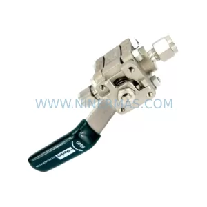
SKU: 016-80686-0 R1E02 2512 A1
Parker 016-80686-0 R1E02 2512 A1 Retrofit Safety Relief Module
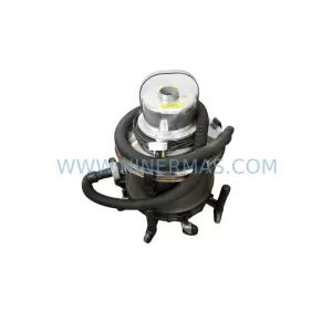
SKU: 605-Z-230CE 0190-08538 CDN127-4 114RR-BJ-000-000
Parker 605-Z-230CE-0190 Retrofit DC Drive for Legacy Systems
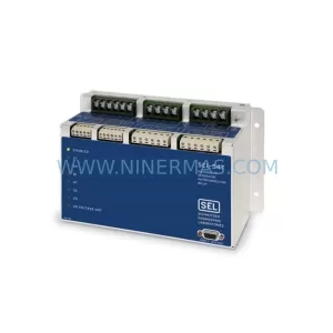
SKU: 890CS-532320B0--B00-U
Parker 890CS-532320B0-B00-U Retrofit Drive for Legacy Systems
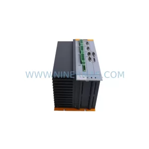
SKU: C3S150V4F11 I20 T11 M00
Parker C3S150V4F11 I20 T11 M00 Retrofit-Compatible Servo Drive
Catalog Continuation
Alternative parts within PLC & Industrial Automation Modules.
Stay inside the same system family when you need substitutes, adjacent modules, or a broader shortlist for procurement review.
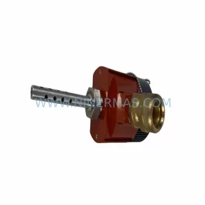
SKU: TRY/PRG/4-20MA/10-30DC
MOORE TRY/PRG/4-20MA/10-30DC Service-Ready Spare Part
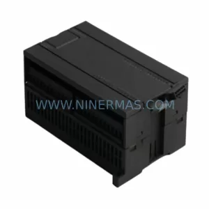
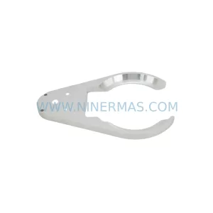
SKU: 5085-404901-11 12INCH 2910-202413-12 404200XRMPD2H14 7-249717
TEL 5085-404901-11 Service-Ready Spare Part for Industrial Maintenance
SKU: DIP011 05-058-011
SIGMATEK DIP011 05-058-011 Service-Ready Spare Part