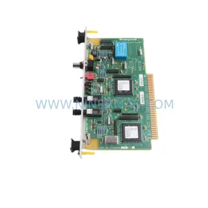
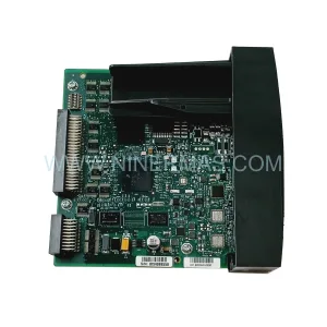
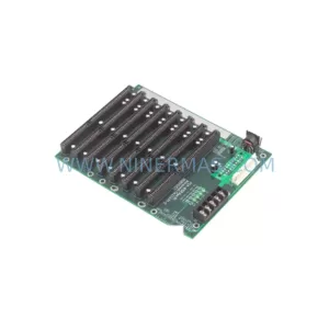
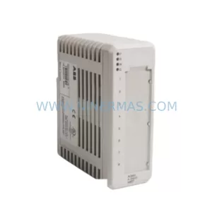
Original Industrial Spare Part
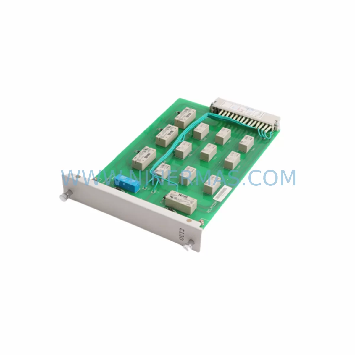
NARI-RELAYS OUT2 Service-Ready Spare Part for Industrial Maintenance
Verify the part, confirm the platform family, and move straight into quotation with the right commercial details.
RFQ Ready
- SKUOUT2
- CategoryDCS Distributed Control Systems
- BrandNARI-RELAYS
- SupportAvailability, lead time, condition, and shipping coordination
How Buyers Usually Use This Page
- Confirm the exact part number and platform family before sending the quote request.
- Use direct email when quantity, condition, and destination are already defined internally.
- Switch to the broader brand or category archive when you need alternates nearby.
Series Navigation
Move through the most common platform families behind this part.
Product RFQ
Send this part directly for quotation.
Include quantity, required condition, destination country, and target delivery timing. Current reference: NARI-RELAYS OUT2 Service-Ready Spare Part for Industrial Maintenance with SKU OUT2.
NARI-RELAYS OUT2 Service-Ready Spare Part for Industrial Maintenance
The NARI-RELAYS OUT2 is a dedicated output relay module engineered for industrial control and protection relay systems within the NARI-RELAYS product family. Designed to meet the demanding requirements of power generation, transmission substations, and process automation environments, the OUT2 module provides reliable digital output switching for trip commands, alarm annunciation, and interlock circuits. For maintenance engineers managing aging relay panels and DCS/PLC-integrated protection systems, sourcing a verified, service-ready OUT2 spare is critical to minimising unplanned downtime and sustaining system integrity across long operational lifecycles.
NINERMAS supplies the NARI-RELAYS OUT2 as a tested, original-specification spare part backed by a 12-month warranty. Each unit undergoes pre-shipment functional verification to confirm output contact ratings, coil energisation response, and terminal integrity before dispatch. Whether you are replenishing your substation spare parts inventory, responding to an emergency relay failure, or executing a scheduled annual overhaul, the OUT2 is available for rapid fulfilment with full documentation support.
Spare Maintenance Table
| Parameter | Specification |
|---|---|
| Part Number / SKU | OUT2 |
| Brand | NARI-RELAYS |
| Module Type | Output Relay Module |
| Series | NARI-RELAYS Protection & Control Series |
| Output Type | Digital Output (Relay Contact) |
| Typical Application | Trip output, alarm relay, interlock switching in protection relay panels and DCS/PLC systems |
| Compatible Systems | NARI-RELAYS protection relay panels, substation automation systems, DCS/PLC digital output racks |
| Installation Environment | Indoor substation, control room, relay panel cabinet, industrial control enclosure |
| Origin | China (CN) |
| Condition | Original, new or refurbished-to-spec (confirmed at order) |
| Pre-Shipment Testing | Output contact continuity, coil energisation, insulation resistance, terminal torque check |
| Warranty | 12 Months from date of shipment |
| Lead Time | Subject to stock availability — contact for confirmation |
| Maintenance Recommendation | Inspect output contacts and coil resistance annually; replace at first sign of contact welding, coil overheating, or erratic trip response |
Maintenance Planning for Continuous Operation
When a NARI-RELAYS OUT2 output relay module is identified for replacement during a fault investigation or scheduled inspection, experienced maintenance engineers treat this as a trigger for a broader system health review. Output relay failures rarely occur in isolation — they are frequently preceded or accompanied by degradation in adjacent components sharing the same protection relay panel or control cabinet.
Begin by auditing the auxiliary power supply module feeding the relay panel. Unstable DC auxiliary voltage — commonly 110 VDC or 220 VDC in substation environments — accelerates coil insulation breakdown and contact erosion in output relay modules. If the OUT2 has failed prematurely, the panel power supply unit should be load-tested and its output ripple measured before the replacement module is commissioned.
Next, inspect the input relay module (IN series) paired with the OUT2 in the same protection relay chassis. Input and output modules in NARI-RELAYS systems share backplane signal paths; a degraded input module can generate spurious trip commands that stress output relay contacts beyond their rated switching capacity. Replacing the OUT2 without verifying the IN module condition risks repeat failure within a short operational period.
The CPU or logic processing module within the protection relay should also be checked for firmware integrity and communication health. In integrated substation automation architectures, the OUT2 receives trip commands via internal bus from the main processing unit. Any latency or signal corruption at the CPU level will manifest as delayed or missed trip outputs — a safety-critical condition in power system protection applications.
For relay panels interfaced with SCADA or substation automation systems via IEC 61850 or DNP3 communication modules, verify that the communication interface card is correctly mapped to the OUT2 channel assignments after module replacement. Incorrect channel mapping post-replacement is a common commissioning error that results in incorrect remote indication of trip status.
Terminal blocks and wiring harnesses connected to the OUT2 output contacts should be inspected for insulation discolouration, loose ferrules, and contact oxidation — particularly on trip circuit wiring routed to circuit breaker coils. Corroded or loose connections at the output terminal strip can cause intermittent trip failures that are difficult to diagnose without systematic wiring inspection.
Where the OUT2 is part of a busbar protection or differential protection relay scheme, the signal isolators and interposing relay modules in the trip circuit should be tested for correct operation. Signal isolation components degrade over time in high-humidity or high-temperature environments and can introduce impedance that prevents reliable trip command transmission.
Finally, review the HMI or local operator panel associated with the relay bay. After OUT2 replacement, perform a full functional test of all output channels from the HMI to confirm that alarm and trip indications are correctly displayed and that the replacement module is fully integrated into the protection scheme logic. Maintain a documented record of the replacement in the relay panel maintenance log, including the pre- and post-replacement test results, to support future lifecycle planning and regulatory compliance.
Site Replacement Workflow
Replacing the NARI-RELAYS OUT2 on-site requires a structured approach to ensure system compatibility, personnel safety, and minimal interruption to protection coverage. The following workflow is recommended for maintenance and commissioning engineers:
Step 1 — Isolation and Permit to Work: Obtain a valid permit to work for the relay panel. Isolate the auxiliary DC supply to the output relay module using the designated isolating switch or fuse. Confirm isolation with a calibrated voltage tester before proceeding.
Step 2 — Documentation Review: Retrieve the relay panel wiring diagram and the OUT2 terminal assignment schedule. Photograph the existing wiring and terminal connections before disconnection to provide a reference for reconnection.
Step 3 — Module Removal: Disconnect output wiring from the OUT2 terminal strip in sequence, labelling each conductor. Release the module retention mechanism (typically a front-panel locking lever or DIN rail clip) and withdraw the OUT2 from the relay chassis or panel mounting position.
Step 4 — Replacement Module Inspection: Inspect the replacement NARI-RELAYS OUT2 for physical damage, confirm the part number matches the removed unit, and verify the pre-shipment test certificate supplied by NINERMAS.
Step 5 — Installation and Wiring: Insert the replacement OUT2 into the chassis slot, secure the retention mechanism, and reconnect output wiring in reverse sequence using the reference photographs and terminal schedule. Apply correct torque to all terminal screws.
Step 6 — Functional Testing: Restore auxiliary DC supply and perform a channel-by-channel output test using the relay panel test facilities or an external test set. Verify that each output contact operates correctly and that trip circuit continuity is confirmed at the circuit breaker end.
Step 7 — System Recommissioning: Restore the protection scheme to service, update the maintenance log, and notify the control room or SCADA operator that the relay bay is back in service. Retain the removed OUT2 module for failure analysis if required.
This structured replacement workflow reduces the risk of wiring errors, ensures compatibility verification before recommissioning, and supports a complete audit trail for maintenance records — all of which are essential for regulated power system and industrial process environments.
Spare Parts Support FAQ
Q1: How do I confirm that the NARI-RELAYS OUT2 supplied by NINERMAS is compatible with my existing relay panel?
Provide your relay panel model number, the existing OUT2 part number label, and any available wiring diagram references when placing your enquiry. NINERMAS will cross-reference these details against our product records to confirm compatibility before shipment. Where panel documentation is unavailable, our technical team can assist with compatibility assessment based on the relay series and application description.
Q2: What pre-shipment testing does NINERMAS perform on the OUT2 before dispatch?
Each NARI-RELAYS OUT2 unit is tested for output contact continuity across all channels, coil energisation at rated auxiliary voltage, insulation resistance between output contacts and coil circuit, and terminal block integrity. A test record is available upon request and can be included with the shipment documentation for your maintenance records.
Q3: Can NINERMAS support long-term or scheduled supply of the OUT2 for annual maintenance programmes?
Yes. NINERMAS offers long-term spare parts supply agreements for critical industrial components including the NARI-RELAYS OUT2. Scheduled delivery programmes can be arranged to align with your annual overhaul calendar, ensuring that verified spare modules are available on-site before planned maintenance windows without the lead time risk associated with spot purchasing.
Q4: What does the 12-month warranty cover for the NARI-RELAYS OUT2?
The 12-month warranty covers manufacturing defects, premature component failure under normal operating conditions, and any functional non-conformance identified during installation and commissioning. The warranty period commences from the date of shipment. Warranty claims require the return of the defective unit with a completed failure report. NINERMAS will provide a replacement unit or repair service subject to failure analysis findings. Damage resulting from incorrect installation, overvoltage events, or operation outside specified parameters is excluded from warranty coverage.
| Product Series | Other series |
|---|
Catalog Continuation
Alternative parts within DCS Distributed Control Systems.
Stay inside the same system family when you need substitutes, adjacent modules, or a broader shortlist for procurement review.