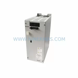
Original Industrial Spare Part
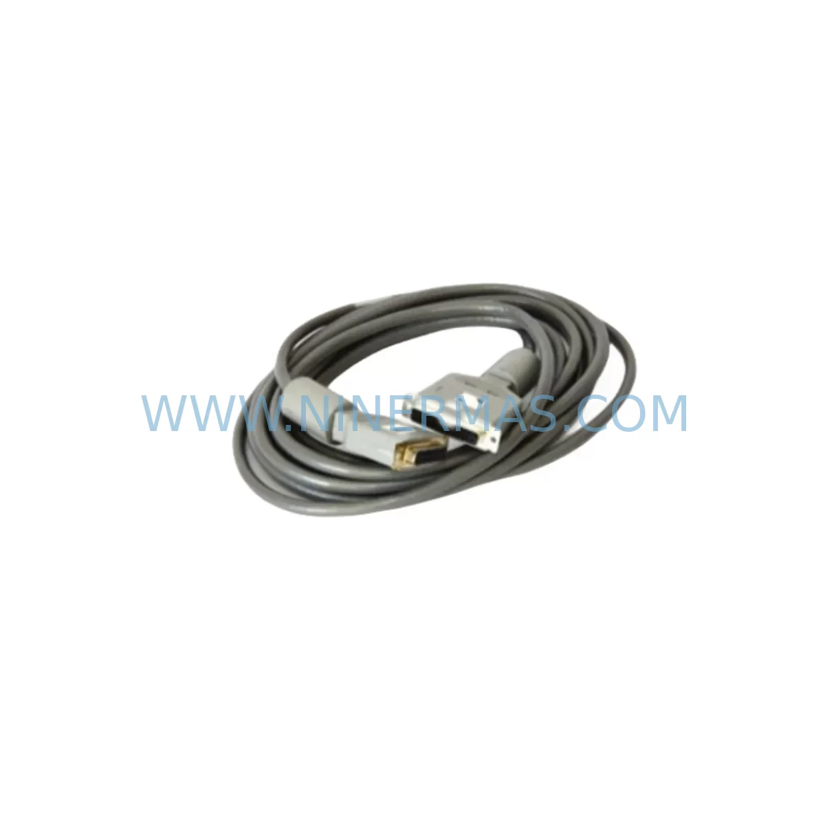
MOORE 16137-148 Retrofit-Compatible I/O Bus Cable for Legacy Systems
Verify the part, confirm the platform family, and move straight into quotation with the right commercial details.
RFQ Ready
- SKU16137-148
- CategoryPLC & Industrial Automation Modules
- BrandMoore
- SupportAvailability, lead time, condition, and shipping coordination
How Buyers Usually Use This Page
- Confirm the exact part number and platform family before sending the quote request.
- Use direct email when quantity, condition, and destination are already defined internally.
- Switch to the broader brand or category archive when you need alternates nearby.
Series Navigation
Move through the most common platform families behind this part.
Product RFQ
Send this part directly for quotation.
Include quantity, required condition, destination country, and target delivery timing. Current reference: MOORE 16137-148 Retrofit-Compatible I/O Bus Cable for Legacy Systems with SKU 16137-148.
MOORE 16137-148 Retrofit-Compatible I/O Bus Cable for Legacy Systems
The MOORE 16137-148 is a retrofit-compatible I/O bus cable engineered to support the modernization of legacy distributed control systems (DCS) and programmable logic controller (PLC) platforms where original MOORE Industries wiring infrastructure has reached end-of-life or is no longer available through standard supply channels. As industrial facilities face increasing pressure to extend the operational life of aging control architectures while managing downtime risk, the 16137-148 provides a reliable, drop-in compatible interconnect solution that preserves existing backplane topology, terminal wiring assignments, and module addressing schemes without requiring full system redesign.
In retrofit and upgrade projects involving MOORE Industries control platforms, the I/O bus cable serves as the physical backbone connecting I/O modules, signal conditioners, and communication interfaces to the central processor or remote I/O rack. The 16137-148 is specifically dimensioned and terminated to match the original factory specification, ensuring that replacement does not introduce impedance mismatches, connector incompatibilities, or signal integrity issues that could compromise loop accuracy or trigger nuisance alarms during commissioning. Engineers planning a control cabinet upgrade or panel refurbishment should verify cable routing clearance, connector locking mechanism condition, and backplane slot alignment before installation.
When integrating the 16137-148 into an existing MOORE Industries rack assembly, technicians should confirm that the host backplane — whether a standard 4-slot, 8-slot, or 16-slot chassis — retains its original bus termination resistors and that no prior cable substitution has altered the pinout sequence. The cable is compatible with MOORE Industries signal isolators, transmitters, and I/O interface modules commonly found in legacy process control panels, including units in the MOORE 535, 550, and 560 product families. Where the original rack also houses a MOORE 353 or 354 controller module, the 16137-148 must be routed to avoid interference with the controller’s front-panel programming port and status LED array.
For facilities undertaking a phased migration from a MOORE Industries DCS to a modern PLC or distributed I/O platform — such as transitioning field signals to a Rockwell Automation ControlLogix or Siemens S7-300 system — the 16137-148 can remain in service during the interim period to maintain signal continuity on loops that have not yet been migrated. This approach allows maintenance teams to decommission individual I/O channels one at a time, preserving HMI screen associations, historian tag mappings, and alarm setpoints on the legacy system while the new platform is being configured and tested in parallel. Communication protocol migration, particularly from proprietary MOORE bus protocols to HART, PROFIBUS-DP, or Modbus RTU, should be validated at the field device level before the legacy cable infrastructure is retired.
Power supply capacity is a critical verification point in any retrofit involving the 16137-148. The existing 24 VDC or 120 VAC rack power supply must be assessed for available headroom before adding replacement modules or expanding I/O capacity. If the retrofit plan includes installing additional MOORE signal conditioners, loop-powered transmitter interfaces, or a MOORE 15700 series power supply module, the total current draw across all backplane slots must be recalculated to ensure the supply remains within its rated output. Undersized power supplies are a leading cause of intermittent faults and unexplained module resets during post-retrofit commissioning.
Installation space confirmation is equally important. The 16137-148 cable assembly has a defined bend radius and minimum routing clearance that must be respected within the control cabinet. In compact panel designs where a MOORE rack shares enclosure space with a third-party PLC, motor drive, or communication gateway, cable management must be planned to prevent mechanical stress on the connector bodies and to maintain separation from high-voltage wiring runs. Where the original cable routing path has been modified by previous maintenance interventions, a physical inspection of the cable tray and conduit entries should be completed before the new cable is dressed and secured.
Upgrade Compatibility Table
| Parameter | Details |
|---|---|
| Part Number | MOORE 16137-148 |
| Cable Function | I/O Bus Interconnect for MOORE Industries Rack Systems |
| Compatible Platforms | MOORE Industries DCS / Signal Conditioning Racks (535, 550, 560 series and related) |
| Connector Type | OEM-matched, factory-pinout compatible |
| Installation Requirement | Verify backplane slot alignment, bus termination, and bend radius clearance |
| Communication Compatibility | Compatible with HART, Modbus RTU, and PROFIBUS-DP migration paths when used in phased retrofit |
| Replacement Recommendation | Direct drop-in replacement for original MOORE 16137-148; no firmware or address reconfiguration required |
| Commissioning Notes | Confirm power supply headroom, module addressing, and HMI tag mapping before cutover |
| Warranty | 12 Months from date of shipment |
Retrofit Planning for Existing Automation Systems
A successful retrofit using the MOORE 16137-148 requires a structured pre-installation review that addresses every layer of the control system stack. At the hardware level, the technician must document the current slot population of the host rack, noting the position of each I/O module, signal isolator, and communication interface card. Where the rack includes a MOORE 15100 series analog input module or a MOORE 15200 series analog output module, the bus cable routing must be confirmed against the module’s backplane connector orientation to avoid forced-fit installation that could damage the connector housing.
At the software and configuration level, the existing program logic stored in the MOORE 353 or 354 controller — or in a connected Siemens S5 or Allen-Bradley SLC 500 host system — must be backed up and version-controlled before any physical work begins. Module I/O addresses, scaling parameters, and alarm limits should be exported and archived. If the retrofit also involves replacing a MOORE 15500 series communication module to support a new Modbus TCP or EtherNet/IP link, the updated module address map must be validated against the host PLC’s I/O configuration table before the new cable is energized.
Signal isolation requirements should be reviewed for each loop that passes through the retrofitted rack. Where the original design relied on MOORE Industries loop-powered signal conditioners or a MOORE 15300 series signal isolator to provide galvanic separation between field devices and the control system, the replacement cable must not introduce ground loops or alter the isolation barrier characteristics. A loop resistance check and insulation resistance test on the completed cable assembly is recommended before the rack is returned to service.
For facilities that also need to replace a MOORE programming cable or handheld configuration tool to re-commission modules after the bus cable replacement, the 16137-148 installation should be sequenced to allow unobstructed access to each module’s front-panel configuration port. Where a MOORE 15700 series rack power supply is also being replaced as part of the same maintenance window, the power supply swap should be completed and verified before the bus cable is installed to avoid energizing the backplane with an unverified supply voltage.
Downtime Control During System Migration
Minimizing unplanned downtime during a MOORE 16137-148 replacement requires a disciplined cutover procedure that protects the integrity of the running process. The recommended approach is to schedule the cable replacement during a planned maintenance window, with the affected control loops placed in manual mode at the DCS or PLC operator station before any physical disconnection occurs. Field operators should be notified of the planned interruption and should confirm that all associated final control elements — control valves, variable speed drives, and interlock outputs — are in a safe, manually controlled state before the rack is de-energized.
Where the process cannot tolerate a full loop interruption, a temporary signal bypass using portable signal generators or loop calibrators can be used to maintain a fixed output to the final control element while the bus cable is replaced. This technique is particularly effective for critical temperature, pressure, or flow control loops where a sustained deviation from setpoint would trigger a process safety interlock or product quality excursion. The bypass signal values should be documented and agreed with the process engineer before the maintenance window begins.
After the MOORE 16137-148 is installed and the rack is re-energized, a systematic loop check should be performed on every I/O channel served by the replaced cable. Each analog input should be verified against a known reference signal, and each analog output should be confirmed at the field device before the loop is returned to automatic control. Digital I/O channels should be exercised through their full on/off cycle to confirm that the bus cable replacement has not introduced any contact resistance or signal level issues. The total commissioning time for a single rack cable replacement is typically two to four hours, depending on the number of active loops and the complexity of the interlock logic.
HMI screen updates and historian configuration changes associated with the retrofit should be completed and tested in the engineering workstation environment before the cutover, so that operators have accurate faceplates and trend displays available immediately after the loop is returned to service. Communication link integrity between the MOORE rack and the host DCS or SCADA system should be confirmed by monitoring the communication status indicators on both the rack module and the host system’s I/O configuration screen for a minimum of 15 minutes after the cutover is complete.
Retrofit Support FAQ
Q1: Is the MOORE 16137-148 a direct replacement for the original factory cable, or does it require any modification to the backplane or module configuration?
The 16137-148 is manufactured to the original MOORE Industries factory specification and is a direct drop-in replacement. No backplane modification, module address reconfiguration, or firmware update is required. The connector pinout, cable length, and termination method match the original part, allowing the replacement to be completed without any changes to the existing rack wiring or module slot assignments.
Q2: What commissioning checks should be performed after installing the 16137-148 to confirm that all I/O channels are functioning correctly?
After installation, perform a full loop check on every analog and digital I/O channel served by the replaced cable. Verify analog input accuracy against a calibrated reference signal, confirm analog output values at the field device, and exercise all digital I/O channels through their full operating cycle. Check the communication status indicators on the rack module and the host system, and monitor for any bus error or module fault alarms for a minimum of 15 minutes before returning loops to automatic control.
Q3: Can the 16137-148 be used in a rack that is being upgraded to support a new communication protocol, such as Modbus RTU or PROFIBUS-DP?
Yes. The 16137-148 provides the physical I/O bus interconnect within the rack and is independent of the communication protocol used by the rack’s communication module. If the retrofit plan includes replacing a legacy MOORE communication module with a new Modbus RTU or PROFIBUS-DP interface card, the 16137-148 can remain in service as the internal bus cable while the new communication module is configured and validated. Protocol migration should be completed and tested at the host system level before the new communication link is placed in service.
Q4: What warranty coverage is provided, and what is the typical lead time for stock availability?
All MOORE 16137-148 cables supplied by Ninermas carry a 12-month warranty from the date of shipment, covering manufacturing defects and functional failures under normal operating conditions. Stock is maintained to support urgent retrofit and breakdown replacement requirements, with same-day or next-business-day dispatch available for in-stock units. For large-quantity orders or scheduled maintenance programs, please contact our sales team to confirm availability and arrange priority allocation.
| Product Series | Legacy |
|---|---|
| Country of Origin | US |
Catalog Continuation
More Moore modules in the catalog.
Use the brand lane to compare nearby part numbers, platform-adjacent modules, and other inquiry-ready listings before sending your final RFQ.
SKU: TRY/PRG/4-20MA/10-30DC
MOORE TRY/PRG/4-20MA/10-30DC Service-Ready Spare Part
SKU: 39ACM28AEN 16139-218
MOORE 39ACM28AEN 16139-218 Safety-Reliable Control Module
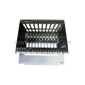
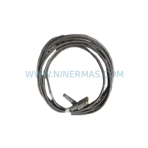
SKU: 16114-171 16114-171/6
Moore 16114-171/6 MODULERAC Spare Part for Industrial Maintenance
Catalog Continuation
Alternative parts within PLC & Industrial Automation Modules.
Stay inside the same system family when you need substitutes, adjacent modules, or a broader shortlist for procurement review.
SKU: 5085-404901-11 12INCH 2910-202413-12 404200XRMPD2H14 7-249717
TEL 5085-404901-11 Service-Ready Spare Part for Industrial Maintenance
SKU: DIP011 05-058-011
SIGMATEK DIP011 05-058-011 Service-Ready Spare Part