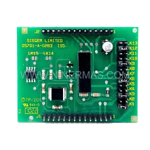
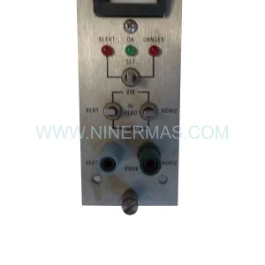
Original Industrial Spare Part
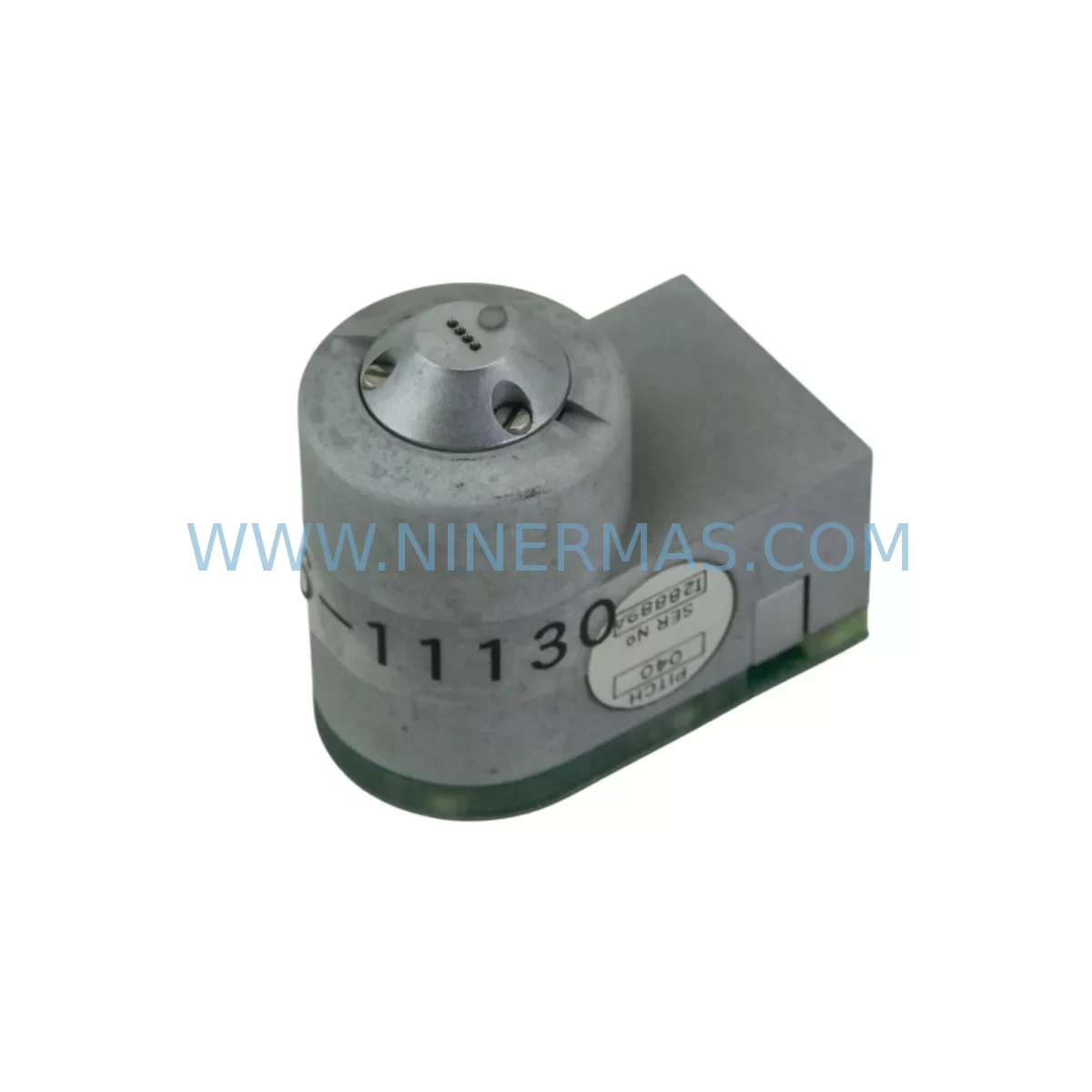
KLA-Tencor 700280-15 Retrofit Probe Head for Legacy Systems
Verify the part, confirm the platform family, and move straight into quotation with the right commercial details.
RFQ Ready
- SKU11130 KLA- B 50-0002-02 020280 700280 15-291107-00
- CategoryTSI & Rotating Machinery Monitoring
- BrandKLA-TENCOR
- SupportAvailability, lead time, condition, and shipping coordination
How Buyers Usually Use This Page
- Confirm the exact part number and platform family before sending the quote request.
- Use direct email when quantity, condition, and destination are already defined internally.
- Switch to the broader brand or category archive when you need alternates nearby.
Series Navigation
Move through the most common platform families behind this part.
Product RFQ
Send this part directly for quotation.
Include quantity, required condition, destination country, and target delivery timing. Current reference: KLA-Tencor 700280-15 Retrofit Probe Head for Legacy Systems with SKU 11130 KLA- B 50-0002-02 020280 700280 15-291107-00.
KLA-Tencor 700280-15 Retrofit Probe Head for Legacy Systems
The KLA-Tencor 700280-15 Probe Head Type B is a precision optical and mechanical assembly originally designed for KLA-Tencor surface inspection and wafer metrology platforms. As semiconductor fabs and advanced packaging lines continue to operate legacy inspection equipment well beyond its original design lifecycle, sourcing a verified, retrofit-compatible replacement for the 700280-15 has become a critical supply chain challenge. NINERMAS maintains ready stock of this probe head assembly, pre-shipment tested and backed by a 12-month warranty, to support uninterrupted production continuity on aging inspection systems.
The 700280-15 Probe Head Type B interfaces directly with the optical column and signal conditioning subsystem of its host platform. When the original unit fails or degrades — typically presenting as focus drift, signal noise, or complete loss of detection sensitivity — the replacement process requires careful attention to mechanical alignment, optical path calibration, and electrical interface compatibility. Engineers undertaking this replacement should verify the probe head’s connector pinout against the host system’s backplane wiring harness before installation, as minor revision differences between the 020280 and 700280 sub-assemblies can affect signal routing at the detector interface board.
Upgrade Compatibility Table
| Parameter | Details |
|---|---|
| Part Number | 700280-15 / 291107-00 (sub-assembly ref: 020280, KLA-B 50-0002-02) |
| Brand | KLA-Tencor |
| Type | Probe Head Type B — Optical/Mechanical Assembly |
| Interface | Multi-pin connector to optical column backplane; compatible with KLA-Tencor SP-series and legacy inspection platforms |
| Installation Requirement | Precision torque tool; optical alignment jig recommended; clean-room handling (Class 100 or better) |
| Communication Compatibility | Analog signal output; compatible with host VME-based signal processing boards |
| Replacement Recommendation | Direct drop-in for 700280-15; verify sub-assembly revision against host system BOM before installation |
| Commissioning Focus | Optical focus calibration, detector gain normalization, signal baseline verification |
| Warranty | 12 Months — covers manufacturing defects and functional performance under normal operating conditions |
Retrofit Planning for Existing Automation Systems
Replacing the 700280-15 Probe Head Type B is rarely an isolated task. In most legacy KLA-Tencor inspection system retrofits, the probe head replacement is part of a broader effort to restore or extend the operational life of the entire inspection cell. Engineers should approach this as a system-level intervention rather than a simple component swap.
Before removing the failed probe head, document the current optical alignment parameters stored in the host controller — typically a VME-based SPARC CPU board or equivalent embedded controller — as these calibration offsets will need to be re-entered or re-derived after the new probe head is seated. If the host system uses a KLA-Tencor 2132 or 2135 inspection controller, the calibration data is stored in non-volatile memory on the signal processing board and can be exported via the system’s diagnostic terminal before the swap begins.
The probe head connects to the optical column through a precision mechanical mount and a multi-conductor signal cable that routes to the detector interface board inside the electronics enclosure. During replacement, inspect the mating connector on the detector interface board for pin corrosion or mechanical damage — this connector is a common secondary failure point on systems that have experienced probe head degradation. If the detector interface board itself shows signs of signal drift or intermittent output, it is advisable to replace it concurrently with the 700280-15 probe head to avoid a repeat service event.
Power supply integrity is another critical checkpoint. The probe head’s internal illumination and detector circuits draw regulated DC power from the system’s internal power distribution board. Verify that the relevant supply rails — typically +5 V, +12 V, and ±15 V — are within specification before energizing the new probe head. A marginal power supply that was masked by the failed probe head’s reduced current draw may cause premature failure of the replacement unit. If the system uses a KLA-Tencor OEM power supply module in the VME rack, measure output voltages under load before proceeding.
For systems where the probe head replacement is part of a broader I/O expansion or communication protocol migration — for example, upgrading from legacy GPIB instrument control to Ethernet-based automation — the 700280-15 replacement should be completed and verified before the communication layer changes are implemented. Mixing mechanical and software changes in a single maintenance window significantly increases the risk of ambiguous fault conditions during commissioning. Related components that are commonly addressed in the same retrofit window include the optical column shutter assembly, the wafer stage encoder feedback module, the system’s fiber optic illumination link, and the signal isolation board that buffers the probe head output before it reaches the VME analog input card. On older platforms, the backplane ribbon cable connecting the probe head signal path to the main chassis may also require inspection and replacement if it shows signs of insulation degradation.
Where the host system includes a KLA-Tencor HMI workstation running legacy inspection recipe software, verify that the probe head type identifier stored in the recipe configuration matches the replacement unit’s type designation. A mismatch between the software’s expected probe head type and the installed hardware can result in incorrect sensitivity scaling and false defect counts, which may not be immediately obvious during initial post-replacement verification runs.
Downtime Control During System Migration
Minimizing unplanned downtime during a 700280-15 probe head replacement requires advance preparation and a structured commissioning sequence. The most effective approach is to pre-stage the replacement probe head in the facility’s metrology lab for incoming inspection and functional verification before the production system is taken offline. NINERMAS ships each 700280-15 unit with a pre-shipment test report confirming optical output characteristics and electrical interface continuity, which provides a baseline for incoming inspection and reduces the time required to validate the replacement unit before installation.
Plan the replacement during a scheduled maintenance window rather than as an emergency response to a complete system failure. If the probe head is showing early signs of degradation — reduced signal amplitude, increased noise floor, or intermittent focus errors — order the replacement unit while the system is still operational. This approach allows the engineering team to prepare the calibration procedure, gather the required tooling, and review the system’s current alignment parameters without time pressure.
During the replacement itself, protect the original program logic and recipe database by creating a full system backup before any hardware changes are made. On VME-based KLA-Tencor platforms, this typically involves exporting the recipe files from the host workstation and saving the controller’s non-volatile memory contents to an external storage device. After the new probe head is installed and the system is powered up, follow the manufacturer’s optical alignment and calibration sequence in full before running production wafers. Skipping or abbreviating the calibration sequence to reduce downtime is the most common cause of post-replacement performance issues on these platforms.
With a pre-staged, tested replacement unit and a prepared commissioning procedure, most 700280-15 probe head replacements can be completed within a single 8-hour maintenance shift, including optical alignment and initial qualification runs.
Retrofit Support FAQ
Q: Is the 700280-15 a direct replacement for the 291107-00 sub-assembly reference?
A: The 700280-15 is the top-level assembly part number; 291107-00 is a sub-assembly reference used in KLA-Tencor’s internal BOM structure. In most cases, ordering the 700280-15 as a complete assembly covers the 291107-00 sub-component. Confirm with your system’s BOM revision before ordering if your platform uses a split-assembly service approach.
Q: What commissioning steps are required after installation?
A: After mechanical installation and connector seating, the system requires optical focus calibration, detector gain normalization, and signal baseline verification using the host system’s built-in diagnostic routines. On KLA-Tencor SP-series platforms, this is performed through the system’s calibration menu. Allow a minimum of 2 hours for the probe head to thermally stabilize before running final qualification wafers.
Q: Has the replacement unit been tested before shipment?
A: Yes. Every 700280-15 unit shipped by NINERMAS undergoes pre-shipment functional testing covering optical output, electrical interface continuity, and mechanical alignment. A test report is included with each shipment. The unit is covered by a 12-month warranty from the date of shipment.
Q: What is the typical lead time and stock availability?
A: NINERMAS maintains inventory of the 700280-15 Probe Head Type B for immediate dispatch. Standard lead time for in-stock units is 3–7 business days for international shipments. For urgent requirements, expedited shipping options are available. Contact our team to confirm current stock levels and delivery timelines for your region.
| Product Series | Legacy |
|---|
Catalog Continuation
Alternative parts within TSI & Rotating Machinery Monitoring.
Stay inside the same system family when you need substitutes, adjacent modules, or a broader shortlist for procurement review.
SKU: TM0181-A40-B01
PROVIBTECH TM0181-A40-B01 Safety-Reliable Vibration Monitor
SKU: 330904-00-08-10-01-00
Bently Nevada 330904-00-08-10-01-00 Safety-Reliable Proximity Transducer
SKU: 330881-16-00-200-06-02
Bently Nevada 330881-16-00-200-06-02 Service-Ready Spare Part