Original Industrial Spare Part
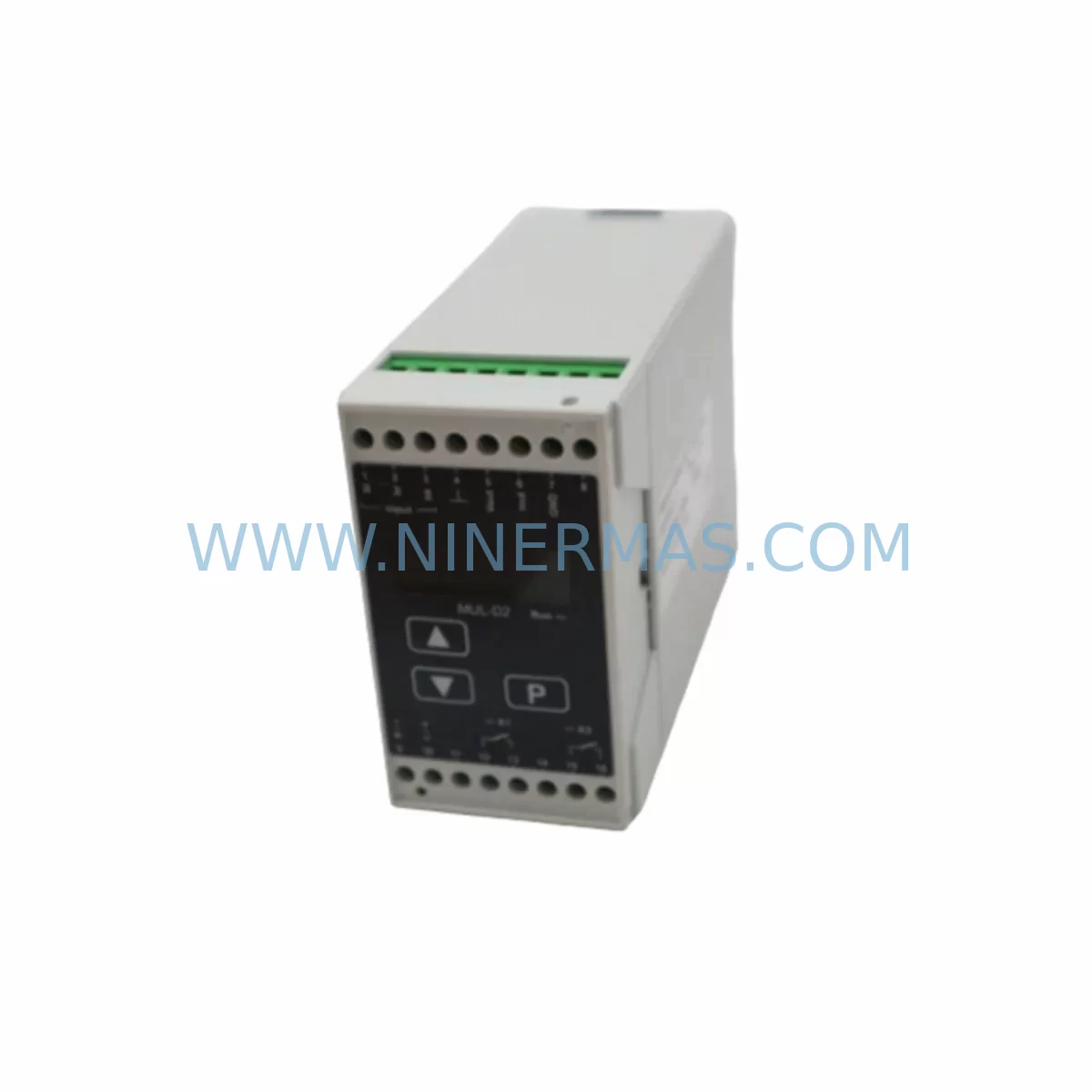
KFG MUL-D2 Service-Ready Spare Part for Industrial Maintenance
Verify the part, confirm the platform family, and move straight into quotation with the right commercial details.
RFQ Ready
- SKUMUL-D2
- CategoryTSI & Rotating Machinery Monitoring
- BrandKFG
- SupportAvailability, lead time, condition, and shipping coordination
How Buyers Usually Use This Page
- Confirm the exact part number and platform family before sending the quote request.
- Use direct email when quantity, condition, and destination are already defined internally.
- Switch to the broader brand or category archive when you need alternates nearby.
Series Navigation
Move through the most common platform families behind this part.
Product RFQ
Send this part directly for quotation.
Include quantity, required condition, destination country, and target delivery timing. Current reference: KFG MUL-D2 Service-Ready Spare Part for Industrial Maintenance with SKU MUL-D2.
KFG MUL-D2 Service-Ready Spare Part for Industrial Maintenance
The KFG MUL-D2 is an original spare part from KFG’s LEVEL series potentiometric transducer range, engineered for continuous-duty level measurement in industrial automation environments. Maintenance engineers and procurement teams managing aging control systems rely on the MUL-D2 to restore accurate level sensing without system redesign or costly downtime. Whether you are responding to an unplanned shutdown, executing a scheduled annual overhaul, or building a proactive spare parts inventory, the MUL-D2 delivers the dimensional and electrical compatibility required for direct drop-in replacement in existing LEVEL series installations.
At NINERMAS, every MUL-D2 unit is sourced from authorized supply channels, individually inspected, and function-tested prior to dispatch. Our 12-month warranty covers manufacturing defects and ensures your maintenance team has recourse if a unit fails in service. We maintain buffer stock specifically for legacy KFG LEVEL series components, supporting long-term procurement programs for facilities that cannot afford supply interruptions on critical measurement loops.
Spare Maintenance Table
| Parameter | Specification |
|---|---|
| Manufacturer | KFG |
| Part Number / SKU | MUL-D2 |
| Series | LEVEL |
| Product Type | Potentiometric Transducer |
| Measurement Principle | Potentiometric (resistive displacement sensing) |
| Output Signal | Analog (voltage/current, series-dependent) |
| Supply Voltage | Refer to LEVEL series datasheet (typically 10–30 V DC) |
| Protection Class | IP65 or higher (application-dependent) |
| Mounting / Installation | Direct replacement for existing LEVEL series mounting points |
| Compatibility | KFG LEVEL series control loops; compatible with standard analog I/O modules |
| Application Environment | Industrial automation, process control, tank level monitoring, hydraulic systems |
| Maintenance Recommendation | Inspect wiring, connector integrity, and signal calibration at each replacement |
| Origin | Germany (inferred from KFG brand heritage) |
| Warranty | 12 Months — NINERMAS Quality Assurance |
| Condition | Original, New — Tested Before Shipment |
Maintenance Planning for Continuous Operation
When replacing the KFG MUL-D2 potentiometric transducer in a LEVEL series loop, a disciplined maintenance engineer will treat the replacement as an opportunity to audit the entire measurement circuit and surrounding control cabinet components. Potentiometric transducers are sensitive to supply voltage stability; before commissioning the new MUL-D2, verify that the 24 V DC power supply module feeding the measurement loop is within tolerance and free of ripple. A degraded power supply is a common root cause of premature transducer failure and should be stocked alongside the MUL-D2 in any serious spare parts program.
Inspect the signal cable and field wiring between the MUL-D2 and the analog input card. Corroded terminals, loose ferrules, or damaged cable shielding will introduce noise into the potentiometric signal and cause erratic level readings even with a new transducer installed. Check the terminal blocks and DIN rail connectors in the control cabinet for signs of thermal stress or oxidation — these are consumable components that should be replaced on a defined cycle rather than only on failure.
On the PLC or DCS side, confirm that the analog input module receiving the MUL-D2 signal is functioning correctly. A faulty AI channel can mask a healthy transducer and lead to misdiagnosis. If the system uses a signal isolator or signal conditioner between the field device and the controller, verify its output range and zero/span calibration after the transducer swap. Signal isolators are frequently overlooked during spare parts planning but are critical to measurement integrity.
For systems where the MUL-D2 feeds a safety relay or safety PLC as part of a high-level or overflow protection loop, ensure that the safety function is re-validated after replacement in accordance with your site’s functional safety procedures. Check the relay output module and any associated fuse holders or circuit breakers in the protection circuit. A blown fuse or a relay with worn contacts can prevent the safety function from operating even after a successful transducer replacement.
In hydraulic or fluid power applications, the MUL-D2 may work in conjunction with pressure transducers and flow sensors to provide a complete picture of system state. When scheduling a MUL-D2 replacement, consider whether adjacent pressure measurement points are due for inspection. Bundling these replacements into a single planned maintenance window reduces total downtime and minimizes the number of system shutdowns per year.
Finally, if your facility operates an HMI or SCADA system that displays the level value from the MUL-D2, perform a full-range signal check after installation and confirm that the displayed value matches the physical level. Update the HMI tag documentation and calibration records to reflect the replacement date, part number, and technician sign-off. This traceability is essential for ISO and IEC compliance audits and supports long-term asset lifecycle management.
Site Replacement Workflow
Step 1 — Isolation and Lockout: De-energize the measurement loop and apply LOTO (Lockout/Tagout) to the power supply feeding the MUL-D2. Confirm zero energy state with a calibrated multimeter before disconnecting the transducer.
Step 2 — Documentation: Photograph the existing wiring configuration and record the terminal assignments before removal. Cross-reference with the LEVEL series wiring diagram in your maintenance management system.
Step 3 — Removal: Disconnect the signal cable and supply wiring. Remove the MUL-D2 from its mounting point, noting the mechanical orientation and any sealing arrangements (O-rings, gaskets) that must be replicated on the replacement unit.
Step 4 — Inspection: Before installing the new MUL-D2, inspect the mounting interface, process connection, and cable entry for damage or contamination. Replace any worn seals or cable glands as required.
Step 5 — Installation: Mount the new KFG MUL-D2 in the same orientation as the original. Reconnect wiring per the documented terminal assignments. Ensure cable shielding is correctly terminated at the control cabinet earth bar.
Step 6 — Commissioning: Re-energize the loop and verify the output signal across the full measurement range. Confirm correct reading on the analog input module and HMI display. Record the as-left calibration values in the maintenance log.
Step 7 — Handover: Update the spare parts inventory to reflect consumption of one MUL-D2 unit and initiate a replenishment order to maintain minimum stock levels. Attach the replacement record to the equipment history file.
Spare Parts Support FAQ
Q1: Is the KFG MUL-D2 a direct replacement for the original LEVEL series unit without any parameter adjustment?
In most installations, the MUL-D2 is a direct drop-in replacement for the original unit. However, we recommend verifying the supply voltage, output signal range, and mechanical dimensions against your existing installation before commissioning. If your system has been modified since the original installation, a brief calibration check after replacement is advisable to confirm signal alignment with the analog input module.
Q2: How does NINERMAS verify the condition of MUL-D2 units before shipment?
Every MUL-D2 unit in our inventory undergoes a pre-shipment inspection that includes visual examination, electrical continuity checks, and functional output verification. Units that do not meet our acceptance criteria are quarantined and not dispatched. A test report is available upon request for customers with quality documentation requirements.
Q3: What is the recommended minimum stock quantity for the MUL-D2 in a production facility?
For facilities with multiple LEVEL series measurement points, we recommend maintaining a minimum of two MUL-D2 units on-site. This provides immediate availability for emergency replacement while a replenishment order is in transit. For critical processes where a single measurement failure can trigger a plant shutdown, a higher buffer stock of three to five units is advisable, particularly given the increasing lead times for legacy KFG components.
Q4: Does the 12-month warranty cover field failures caused by installation errors or electrical overstress?
The NINERMAS 12-month warranty covers manufacturing defects confirmed through technical assessment. Failures attributable to incorrect installation, supply voltage outside the specified range, or physical damage are not covered under warranty. To protect your investment, we recommend following the site replacement workflow above and ensuring that the supply circuit is verified before energizing the new unit. Our technical team is available to support fault diagnosis if a warranty claim is required.
| Product Series | Other series |
|---|
Catalog Continuation
Alternative parts within TSI & Rotating Machinery Monitoring.
Stay inside the same system family when you need substitutes, adjacent modules, or a broader shortlist for procurement review.
SKU: TM0181-A40-B01
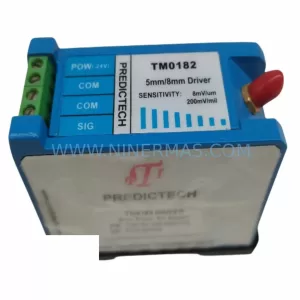
PROVIBTECH TM0181-A40-B01 Safety-Reliable Vibration Monitor
SKU: 330904-00-08-10-01-00
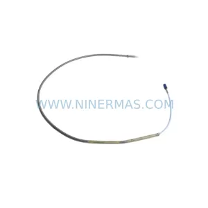
Bently Nevada 330904-00-08-10-01-00 Safety-Reliable Proximity Transducer
SKU: 330881-16-00-200-06-02
Bently Nevada 330881-16-00-200-06-02 Service-Ready Spare Part