Original Industrial Spare Part
INTERNIX PF80-ATHD02 Retrofit-Compatible Safety Module for Legacy Systems
Verify the part, confirm the platform family, and move straight into quotation with the right commercial details.
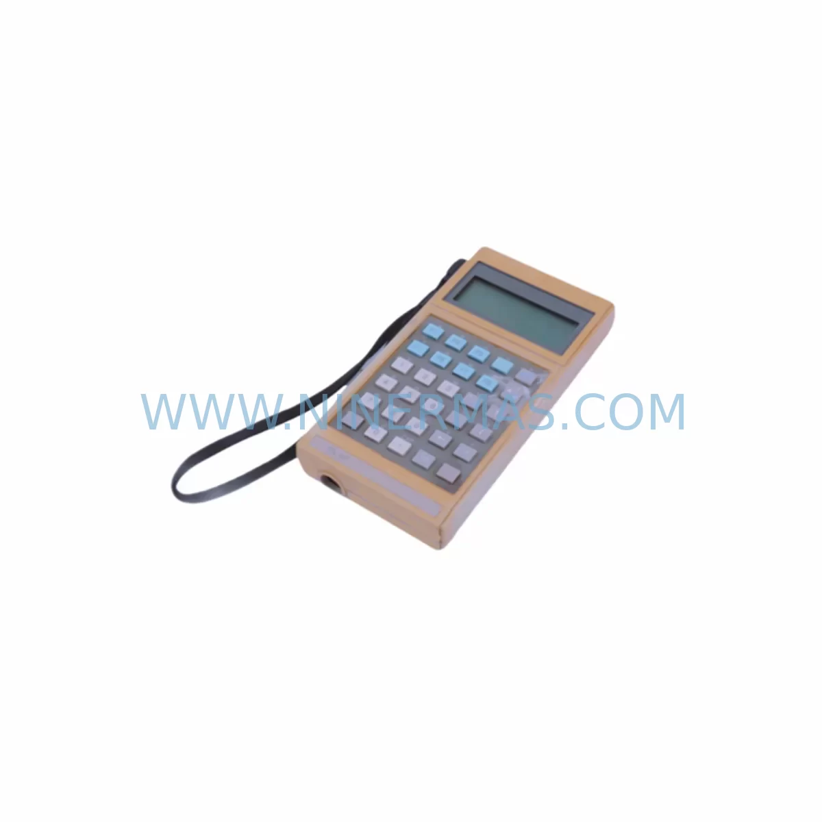
RFQ Ready
- SKUPROFORT80 PF80-ATHD02
- CategorySIS Safety & Redundancy Systems
- BrandINTERNIX
- SupportAvailability, lead time, condition, and shipping coordination
How Buyers Usually Use This Page
- Confirm the exact part number and platform family before sending the quote request.
- Use direct email when quantity, condition, and destination are already defined internally.
- Switch to the broader brand or category archive when you need alternates nearby.
Series Navigation
Move through the most common platform families behind this part.
Product RFQ
Send this part directly for quotation.
Include quantity, required condition, destination country, and target delivery timing. Current reference: INTERNIX PF80-ATHD02 Retrofit-Compatible Safety Module for Legacy Systems with SKU PROFORT80 PF80-ATHD02.
INTERNIX PROFORT80 PF80-ATHD02 Retrofit-Compatible Safety Module for Legacy Systems
The INTERNIX PROFORT80 PF80-ATHD02 is a ruggedized PLC safety module engineered for seamless integration into aging automation infrastructures. As industrial facilities face mounting pressure to extend the operational life of legacy control systems while meeting modern functional safety standards (IEC 61508 / IEC 62061), the PF80-ATHD02 provides a validated, drop-in-compatible upgrade path that minimizes engineering risk and reduces unplanned downtime. Whether you are replacing an end-of-life safety relay, upgrading a discontinued safety PLC module, or expanding I/O capacity within an existing PROFORT80 rack, this module delivers the reliability and compliance your production environment demands.
Upgrade Compatibility Table
| Parameter | PF80-ATHD02 (This Unit) | Typical Legacy Predecessor | Retrofit Notes |
|---|---|---|---|
| Module Form Factor | PROFORT80 Rack-Mount | PROFORT60 / Third-Party Safety Relay | Verify backplane slot pitch; adapter plate may be required for non-PROFORT80 racks |
| Communication Interface | PROFIBUS-DP / PROFINET-ready | Hardwired relay / RS-485 | Protocol migration required; update GSD/GSDML files in engineering station |
| I/O Configuration | Dual-channel digital safety input | Single-channel relay output | Rewire terminal blocks; confirm SIL loop integrity after rewiring |
| Power Supply Requirement | 24 VDC (SELV) | 24 VDC or 120 VAC (varies) | Confirm cabinet PSU capacity; PROFORT80 PS24 power supply recommended |
| Module Address Setting | Software-configurable via PROFORT Studio | DIP switch / rotary dial | Assign node address in PROFORT Studio before first power-on |
| Safety Rating | SIL 2 / PLd (IEC 61508 / EN ISO 13849) | SIL 1 or unrated | Update safety validation documentation and SISTEMA project file |
| HMI Screen Compatibility | Compatible with PROFORT HMI TP700 / TP1200 series | Legacy panel indicators | Update HMI tag database; remap safety status bits to new module address |
| Installation Space | Single-slot PROFORT80 rack unit | DIN-rail mounted relay block | Measure available rack slots; consolidation of multiple relays into one module is common |
| Commissioning Tool | PROFORT Studio v4.x or later | Manual wiring diagram only | Laptop with USB-to-PROFIBUS adapter (e.g., PROFORT PC-ADAPTER USB) required on-site |
| Warranty | 12-Month Warranty — All units shipped by NINERMAS are tested and covered for 12 months from date of delivery | ||
Retrofit Planning for Existing Automation Systems
Successful integration of the PF80-ATHD02 into a live production environment begins well before the module arrives on-site. A structured retrofit plan should account for every layer of the control architecture — from the field device wiring at the terminal block level up through the communication network and into the SCADA or HMI layer.
Start by auditing the existing cabinet layout. In many legacy installations, safety functions are distributed across multiple standalone safety relays — such as PILZ PNOZ X series or Schmersal SRB-E units — wired individually to machine guard switches, light curtains, and emergency stop buttons. Consolidating these into a single PROFORT80 PF80-ATHD02 module not only reduces cabinet footprint but also simplifies the safety logic into a single, auditable program block within PROFORT Studio.
Next, evaluate the backplane and rack infrastructure. If the existing rack is a PROFORT80 BU08 or BU16 backplane unit, the PF80-ATHD02 slots in directly without mechanical modification. For installations migrating from a PROFORT60 platform, a rack adapter or full rack replacement with a new PROFORT80 BU08 backplane will be necessary. Confirm the number of available slots — a typical upgrade scenario involves replacing two or three legacy I/O modules with a single PF80-ATHD02, freeing slots for additional PROFORT80 DI16 digital input modules or PROFORT80 DO08 digital output modules needed for expanded machine control.
Power supply capacity is a critical checkpoint. The PROFORT80 PS24 24VDC power supply module should be verified against the total current draw of all installed modules after the retrofit. Adding the PF80-ATHD02 alongside existing PROFORT80 AI08 analog input modules or communication modules such as the PROFORT80 CM-PNIO PROFINET communication module may push the rack’s power budget close to its rated limit. Always leave a 20% headroom margin.
Terminal block rewiring is the most time-sensitive on-site task. The PF80-ATHD02 uses a 24-pin spring-clamp terminal connector. Map each existing wire from the legacy relay terminal to the corresponding PF80-ATHD02 channel before the maintenance window begins. Pre-label all wires using the new module’s I/O numbering convention. For dual-channel safety loops (e.g., Category 3 / PLd light curtain circuits), both channels must be wired and verified independently before the safety validation test.
On the software side, import the PF80-ATHD02 GSD file into your PROFIBUS master configuration or add the GSDML device profile to your PROFINET controller project. If the controller is a PROFORT80 CPU315S safety CPU, the safety program must be extended to include the new module’s F-address and diagnostic byte mapping. Existing non-safety program blocks typically require no modification, but the safety program (F-program) must be re-compiled, downloaded, and accepted with a safety password before the module can be activated.
HMI screens connected via a PROFORT HMI TP700 or similar operator panel will need their tag databases updated to reflect the new module address. Safety status bits — such as channel fault, discrepancy error, and reintegration request — must be remapped to the new F-address range. This step is frequently overlooked during rushed retrofits and can result in operators receiving no visual feedback on safety faults after the upgrade.
Downtime Control During System Migration
Minimizing production downtime during a safety module retrofit requires a disciplined pre-staging approach. All configuration work — PROFORT Studio project updates, HMI tag remapping, terminal block pre-wiring on a test bench, and safety validation documentation — should be completed and verified before the maintenance window begins. The goal is to reduce on-site hot-work to a defined sequence of mechanical swap, cable connection, address assignment, program download, and functional test.
Preserve the original PLC program by exporting a full project backup from PROFORT Studio before any changes are made. Store this backup on a separate USB drive kept at the machine. If the retrofit encounters an unexpected issue — such as a backplane incompatibility or a communication fault on the PROFIBUS segment — the original configuration can be restored within minutes, returning the line to its previous operating state without data loss.
For continuous-process applications where even a brief stop is costly, consider a parallel-run strategy: install the PF80-ATHD02 in an adjacent rack slot in bypass mode, complete all wiring and software configuration, and perform a full functional test against a simulated safety input before cutting over from the legacy relay. This approach keeps the existing safety circuit live until the new module has been fully validated, reducing the actual switchover to a single relay changeover step that can be completed in under five minutes.
After cutover, perform a structured commissioning sequence: power-on self-test confirmation, channel-by-channel input simulation using a test plug or loop calibrator, safety function trip test (verify that each guarded zone correctly de-energizes the associated output), and PROFIBUS/PROFINET diagnostic check from the controller’s online view. Document all test results in the machine’s safety validation record before releasing the line to production.
Retrofit Support FAQ
Q1: Is the PF80-ATHD02 a direct replacement for legacy PROFORT60 safety modules?
The PF80-ATHD02 is designed for the PROFORT80 platform and is not pin-compatible with PROFORT60 modules. A rack upgrade to the PROFORT80 BU08 or BU16 backplane is required. NINERMAS can supply the complete rack migration kit including the new backplane, PS24 power supply, and CPU315S controller if a full platform upgrade is planned. Contact sale@ninermas.com for a migration BOM.
Q2: What commissioning tools are required on-site?
You will need a laptop running PROFORT Studio v4.x or later, a PROFORT PC-ADAPTER USB (or compatible PROFIBUS/USB interface), and the PF80-ATHD02 GSD/GSDML device file (available from NINERMAS upon purchase). A digital multimeter and a safety relay test plug are recommended for channel verification during the functional test.
Q3: Can the PF80-ATHD02 be wired to third-party safety sensors and light curtains?
Yes. The PF80-ATHD02 accepts standard dual-channel OSSD (Output Signal Switching Device) inputs compatible with IEC 61496-compliant safety light curtains, as well as dry-contact inputs from safety door switches and emergency stop buttons. Confirm the sensor’s output voltage and current rating against the module’s input specifications before wiring.
Q4: What does the 12-month warranty cover, and what is the lead time?
All PF80-ATHD02 units shipped by NINERMAS COMPANY LIMITED carry a 12-month warranty from the date of delivery, covering manufacturing defects and functional failures under normal operating conditions. Units are pre-tested before shipment. In-stock units typically ship within 3–5 business days. For urgent requirements or large-quantity orders, contact sale@ninermas.com or call +0086 187 5021 5667 to confirm availability and expedited shipping options.
| Product Series | Legacy |
|---|
Catalog Continuation
Alternative parts within SIS Safety & Redundancy Systems.
Stay inside the same system family when you need substitutes, adjacent modules, or a broader shortlist for procurement review.
SKU: 6DD1606-3AC0 6DD1600-0AK0
Siemens 6DD1606-3AC0 Safety-Reliable CPU for Critical Control Sites
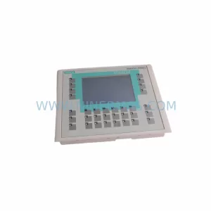
SKU: 6AV6642-0DC01-1AX0
Siemens 6AV6642-0DC01-1AX0 Safety-Reliable HMI Panel