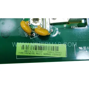
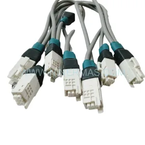
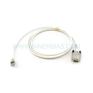
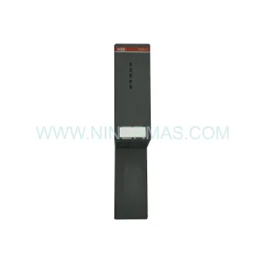
Original Industrial Spare Part
INTEGRAL 9400-00096 Service-Ready Spare Part Industrial
Verify the part, confirm the platform family, and move straight into quotation with the right commercial details.
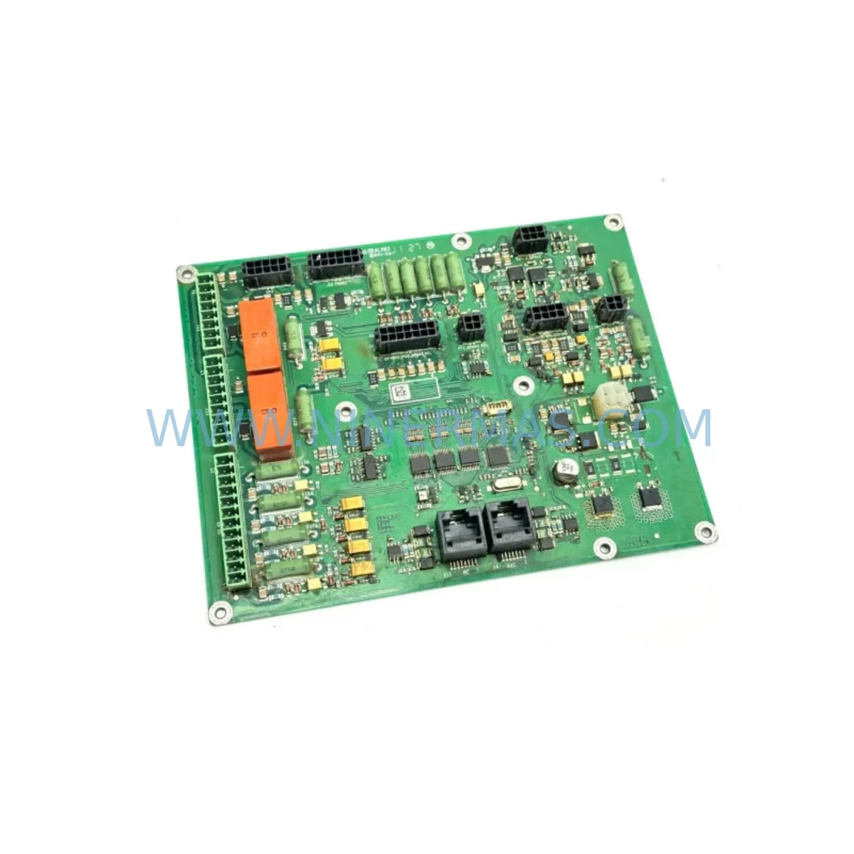
RFQ Ready
- SKU9400-00096 119-8124-00 MG3-3EF-4CEE-4DAD-S1084 0040-18094
- CategoryPLC & Industrial Automation Modules
- BrandINTEGRAL
- SupportAvailability, lead time, condition, and shipping coordination
How Buyers Usually Use This Page
- Confirm the exact part number and platform family before sending the quote request.
- Use direct email when quantity, condition, and destination are already defined internally.
- Switch to the broader brand or category archive when you need alternates nearby.
Series Navigation
Move through the most common platform families behind this part.
Product RFQ
Send this part directly for quotation.
Include quantity, required condition, destination country, and target delivery timing. Current reference: INTEGRAL 9400-00096 Service-Ready Spare Part Industrial with SKU 9400-00096 119-8124-00 MG3-3EF-4CEE-4DAD-S1084 0040-18094.
INTEGRAL 9400-00096 Service-Ready Spare Part Industrial: Spare Part Replacement and Downtime Risk Control
The INTEGRAL 9400-00096 is a critical service-ready spare part designed for industrial maintenance environments where system continuity, rapid fault recovery, and long-term operational reliability are non-negotiable. Cross-referenced with companion part numbers 119-8124-00, MG3-3EF-4CEE-4DAD-S1084, and 0040-18094, this module addresses the demanding requirements of maintenance engineers and procurement specialists managing legacy and active INTEGRAL control architectures. Whether you are executing a planned annual overhaul, responding to an unscheduled line stoppage, or building a strategic spare parts inventory, the 9400-00096 delivers the compatibility, electrical integrity, and supply assurance your operation demands.
INTEGRAL, a recognized name in industrial control and automation hardware, has supplied control modules, power distribution components, and I/O interface assemblies to manufacturing sites across Europe and Asia for decades. The 9400-00096 fits within INTEGRAL’s established control cabinet ecosystem, making it a direct replacement candidate for aging or failed units without requiring system-level redesign or firmware reconfiguration. For maintenance teams operating under strict uptime SLAs, this is a decisive advantage.
Spare Maintenance Table
| Parameter | Specification / Detail |
|---|---|
| Primary Part Number | 9400-00096 |
| Cross-Reference SKUs | 119-8124-00 / MG3-3EF-4CEE-4DAD-S1084 / 0040-18094 |
| Brand | INTEGRAL |
| Product Type | Industrial Control Module / Spare Part |
| Series | INTEGRAL 9400 Series |
| Application | Industrial control cabinets, PLC/DCS systems, automation panels |
| Compatibility | INTEGRAL 9400 Series control systems; cross-compatible with 119-8124-00 and 0040-18094 variants |
| Installation Environment | Industrial control cabinet, DIN-rail or panel-mount |
| Operating Temperature | 0°C to +55°C (standard industrial range) |
| Storage Temperature | -25°C to +70°C |
| Condition | Service-Ready (pre-shipment tested) |
| Maintenance Recommendation | Inspect every 12–24 months; replace on first sign of fault or degraded signal integrity |
| Warranty | 12 Months from date of shipment |
| Lead Time | Subject to stock availability; contact for confirmed lead time |
| Origin | Germany (EU manufactured) |
Maintenance Planning for Continuous Operation
Effective maintenance planning for systems incorporating the INTEGRAL 9400-00096 requires a holistic view of the control cabinet and associated electrical circuits. When replacing or inspecting this module, maintenance engineers should simultaneously evaluate the condition and availability of several interconnected components to prevent cascading failures and reduce the probability of repeat downtime events.
Begin with the 24VDC power supply module feeding the control rack — a degraded or undersized power supply is a leading cause of premature module failure and intermittent faults that are difficult to diagnose under load. Verify output voltage stability and ripple within specification before commissioning the replacement 9400-00096. Alongside the power supply, inspect the terminal block assemblies (such as INTEGRAL or Phoenix Contact DIN-rail terminal strips) for loose connections, oxidation, or thermal discoloration, which can introduce resistance and signal noise into the control loop.
The I/O interface modules adjacent to the 9400-00096 in the same rack should be checked for firmware currency and physical connector integrity. In INTEGRAL 9400 Series architectures, I/O modules such as digital input cards and analog output cards share backplane communication with the primary control module — a fault in one can mask or amplify symptoms in another. Similarly, backplane connectors and bus termination resistors should be inspected for mechanical wear, especially in high-vibration environments.
For systems with fieldbus or industrial Ethernet connectivity, verify the communication module (PROFIBUS DP, PROFINET, or EtherCAT interface card) is operating without CRC errors or timeout faults. Communication instability is frequently misdiagnosed as a module hardware failure when the root cause is a degraded network cable or a faulty RJ45 or D-sub connector on the communication port.
Relay output modules and solid-state relay (SSR) assemblies in the same cabinet should be tested for contact resistance and switching response time. Relay contacts degrade over switching cycles and can introduce latency or false signals into the control sequence. If the 9400-00096 interfaces with motor drives or servo amplifiers, inspect the drive enable signal wiring and any associated signal isolators or optocouplers for leakage current or insulation breakdown.
HMI panels connected to the INTEGRAL system — whether a dedicated INTEGRAL operator panel or a third-party touch panel — should be checked for communication timeout errors and display integrity. An HMI that intermittently loses connection to the controller can trigger unnecessary alarm states and complicate fault diagnosis. Finally, review the fuse and circuit breaker ratings for each supply rail in the cabinet to confirm they remain within specification for the current load profile, particularly if the system has been expanded or modified since original commissioning.
Stocking the 9400-00096 alongside its cross-reference variants (119-8124-00 and 0040-18094) as part of a critical spare parts kit is strongly recommended for sites with no acceptable downtime window. Procurement engineers should also consider holding one spare 24VDC PSU module, one spare digital I/O card, and one spare communication interface module to cover the most statistically probable failure modes in INTEGRAL 9400 Series installations.
Site Replacement Workflow
Replacing the INTEGRAL 9400-00096 on-site follows a structured sequence designed to minimize downtime and eliminate the risk of secondary damage to adjacent components. Before beginning, confirm that the replacement unit’s part number and firmware revision (where applicable) match the installed unit’s documentation. Cross-reference against 119-8124-00 and 0040-18094 to confirm interchangeability in your specific system revision.
Step 1 — Safe Isolation: De-energize the control cabinet following your site’s lockout/tagout (LOTO) procedure. Confirm absence of voltage on all supply rails using a calibrated multimeter before touching any module.
Step 2 — Documentation: Photograph or record all wiring connections, DIP switch settings, and jumper configurations on the existing module before removal. This is critical for legacy systems where original wiring diagrams may be incomplete or unavailable.
Step 3 — Module Removal: Release the module from the backplane or DIN-rail mounting using the manufacturer’s specified extraction tool or lever. Avoid applying lateral force to the connector pins.
Step 4 — Inspection: Inspect the backplane connector and adjacent modules for physical damage, corrosion, or contamination before installing the replacement 9400-00096.
Step 5 — Installation and Configuration: Seat the replacement module firmly, restore all wiring connections per your documentation, and replicate any DIP switch or jumper settings from Step 2.
Step 6 — Commissioning: Re-energize the cabinet in stages. Verify power supply output, confirm module status LEDs indicate normal operation, and run a functional test of all I/O channels before returning the system to production.
This workflow applies equally when upgrading from an end-of-life variant (such as 0040-18094) to the current 9400-00096 production revision, ensuring backward compatibility is maintained without system-level reconfiguration.
Spare Parts Support FAQ
Q1: Is the INTEGRAL 9400-00096 compatible with older 119-8124-00 and 0040-18094 installations?
Yes. The 9400-00096 is cross-referenced against 119-8124-00 and 0040-18094 and is designed as a direct replacement in INTEGRAL 9400 Series control architectures. Compatibility should always be verified against your system’s revision documentation before installation. Our technical team can assist with compatibility confirmation prior to shipment.
Q2: What pre-shipment testing is performed on the 9400-00096?
Every unit undergoes functional verification and electrical parameter testing before dispatch. Testing covers power-on self-test, I/O channel integrity, and communication interface response where applicable. A test report is available upon request. All units are shipped with 12-month warranty coverage from the date of shipment.
Q3: Can you guarantee long-term supply of the 9400-00096 for multi-year maintenance contracts?
Yes. NINERMAS maintains reserved inventory agreements and global sourcing networks specifically for end-of-life and hard-to-source industrial components. We can discuss long-term supply agreements, consignment stock arrangements, and volume pricing for procurement engineers managing multi-site maintenance programs. Contact our team to discuss your specific requirements.
Q4: What is the recommended spare parts strategy for sites running INTEGRAL 9400 Series systems?
We recommend holding a minimum of one 9400-00096 (or cross-reference equivalent) per control cabinet as a critical on-site spare. For sites with multiple cabinets or high-criticality production lines, a centralized spare parts kit including the primary control module, one PSU module, one I/O card, and one communication interface module provides the most cost-effective downtime protection. Annual inventory audits and condition-based replacement cycles of 5–7 years are standard practice for this component class.
| Product Series | Other series |
|---|
Catalog Continuation
Alternative parts within PLC & Industrial Automation Modules.
Stay inside the same system family when you need substitutes, adjacent modules, or a broader shortlist for procurement review.
SKU: TTLM10-11 ELVIF-F 3895-120321-21 TTLD14-12 WCIF-L 3881-020032-11 TTLM11-11 W/TIF-L 3895-120322-21
TEL 3895-120321-21 Service-Ready Spare for Industrial Maintenance
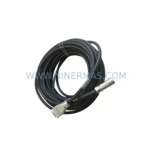
SKU: KR6 00-204-935 00-204-551
KUKA KR6 00-204-935 00-204-551 Retrofit-Compatible Signal Cable for Legacy Systems