Original Industrial Spare Part
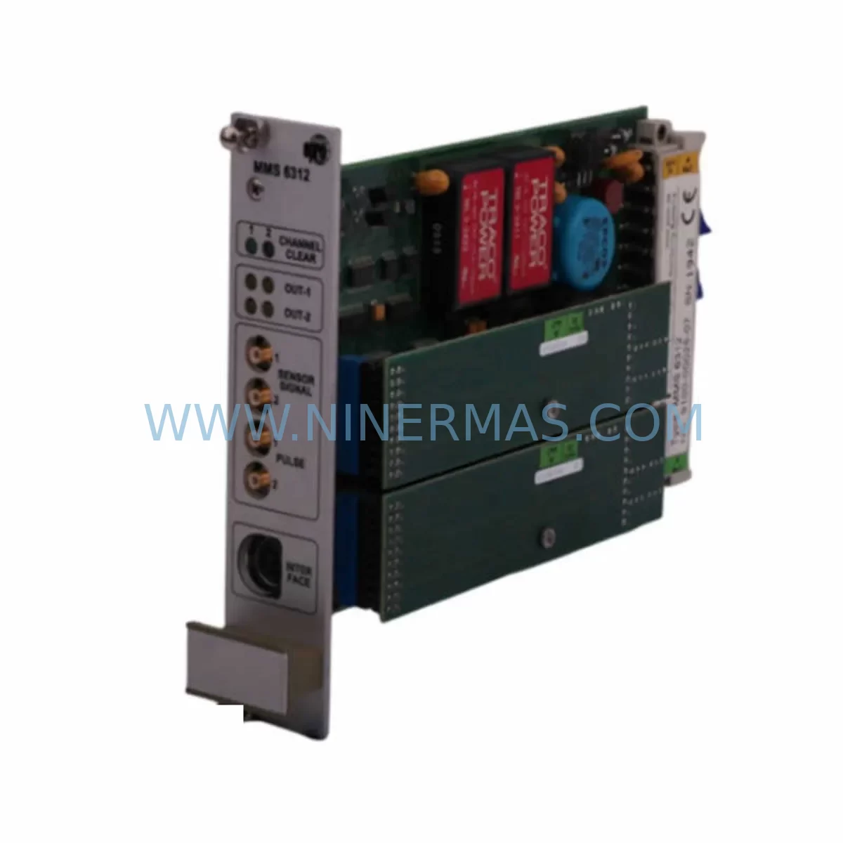
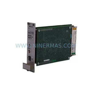
EPRO MMS6312 Retrofit-Compatible Speed Monitor for Legacy Systems
Verify the part, confirm the platform family, and move straight into quotation with the right commercial details.
RFQ Ready
- SKUMMS6312
- CategoryTSI & Rotating Machinery Monitoring
- BrandEPRO
- SupportAvailability, lead time, condition, and shipping coordination
How Buyers Usually Use This Page
- Confirm the exact part number and platform family before sending the quote request.
- Use direct email when quantity, condition, and destination are already defined internally.
- Switch to the broader brand or category archive when you need alternates nearby.
Series Navigation
Move through the most common platform families behind this part.
Product RFQ
Send this part directly for quotation.
Include quantity, required condition, destination country, and target delivery timing. Current reference: EPRO MMS6312 Retrofit-Compatible Speed Monitor for Legacy Systems with SKU MMS6312.
EPRO MMS6312 Retrofit-Compatible Speed Monitor for Legacy Systems
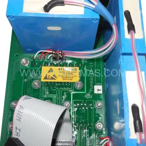
The EPRO MMS6312 is a dual-channel speed monitoring module engineered for seamless integration into aging industrial control architectures. As processing plants, power generation facilities, and heavy manufacturing operations face the end-of-life of their original vibration and speed monitoring platforms, the MMS6312 provides a proven, retrofit-compatible path to restore and extend system functionality without requiring a full platform overhaul. Whether you are replacing a discontinued EPRO module, upgrading a legacy Bently Nevada 3500-series rack, or migrating from an older MMS3000 or MMS6000 series installation, the MMS6312 delivers the measurement accuracy, signal conditioning, and relay output performance your critical rotating machinery protection demands.
Designed for installation in the EPRO MMS6000 modular rack system, the MMS6312 accepts inputs from passive magnetic pickups (MPUs) and active proximity probes, making it directly compatible with existing field wiring in most legacy installations. The module monitors two independent speed channels simultaneously, providing overspeed, underspeed, and zero-speed detection with configurable relay outputs. This dual-channel architecture is particularly valuable during phased migration projects where one channel can remain connected to the legacy system while the second channel is commissioned on the new platform — dramatically reducing planned downtime and protecting continuous production.
For engineers managing a control cabinet upgrade or a full machinery protection system (MPS) modernization, the MMS6312 integrates naturally alongside other MMS6000-series modules including the MMS6110 (single-channel vibration monitor), MMS6120 (dual-channel vibration monitor), MMS6220 (dual-channel displacement monitor), and MMS6350 (temperature and process monitor). The shared rack backplane — typically the MMS6901 or MMS6902 rack chassis — allows mixed-module configurations, so existing I/O wiring, terminal blocks, and cable trays can be retained while individual measurement functions are upgraded module by module.
When replacing a Bently Nevada 3500/25 or 3500/50 speed monitor, or an older EPRO PR6423 proximity probe system, field engineers must verify several critical parameters before commissioning the MMS6312: input signal voltage range, probe gap voltage at operating speed, trigger level thresholds, and relay output wiring polarity. The MMS6312 supports both NPN and PNP proximity sensor inputs, and its front-panel DIP switch configuration allows threshold adjustment without removing the module from the rack — a significant advantage during live system commissioning where adjacent channels must remain in service.
Communication integration is another key consideration in retrofit projects. The MMS6312 connects to the rack’s internal communication bus, which interfaces with plant DCS or SCADA systems via the MMS6820 communication gateway module supporting Modbus RTU or Profibus DP protocols. If your existing control system uses a Siemens S7-300 or S7-400 PLC as the supervisory controller, the Profibus DP interface allows direct integration without additional signal converters. For plants running ABB Freelance or Emerson DeltaV DCS platforms, Modbus RTU mapping tables must be prepared in advance to ensure speed values, relay status bits, and alarm flags are correctly mapped to the existing HMI tag database — preserving operator screen layouts and alarm management logic without reprogramming.
Power supply compatibility is a non-negotiable checkpoint. The MMS6000 rack requires a 24 VDC supply, typically sourced from a dedicated MMS6910 power supply module or an equivalent DIN-rail mounted 24 VDC PSU with sufficient current capacity for the fully populated rack. Before installing the MMS6312, confirm that the existing power supply can support the additional load, particularly if the rack is being expanded from a partial to a full 12-slot configuration. Undersized power supplies are a common root cause of intermittent relay chatter and false trip events during commissioning.
Installation space confirmation is equally important. The MMS6312 occupies a single slot in the MMS6000 rack. If the existing rack is fully populated, a slot must be freed by relocating or decommissioning a redundant module. In compact control cabinets where rack space is limited, the slim-profile design of the MMS6000 series provides an advantage over older, bulkier monitoring platforms. Verify cabinet depth, ventilation clearance, and cable bend radius before finalizing the installation layout.
Pre-shipment testing is standard for every MMS6312 unit supplied by NINERMAS. Each module undergoes functional verification including channel input sensitivity, relay output switching, threshold accuracy, and communication bus response before dispatch. Units are supplied with a 12-month warranty covering manufacturing defects and functional failures under normal operating conditions. Expedited shipping is available for critical plant shutdowns and unplanned outage scenarios.
Upgrade Compatibility Table
| Parameter | Legacy / Replaced Unit | EPRO MMS6312 | Retrofit Notes |
|---|---|---|---|
| Monitoring Channels | 1 or 2 (varies by model) | 2 independent channels | Dual-channel supports phased migration |
| Input Sensor Type | MPU / Proximity Probe | MPU & Active Proximity (NPN/PNP) | Verify probe gap voltage before commissioning |
| Rack / Backplane | MMS3000 / MMS6000 / 3500-series | MMS6000 (MMS6901 / MMS6902) | Rack chassis must be MMS6000 series |
| Communication Protocol | Hardwired relay / Proprietary bus | Modbus RTU / Profibus DP (via MMS6820) | Prepare Modbus/Profibus mapping tables in advance |
| Power Supply | 24 VDC (rack-level) | 24 VDC via MMS6910 or equivalent PSU | Confirm PSU current capacity for full rack load |
| Relay Outputs | SPDT relay (varies) | Configurable relay outputs per channel | Verify wiring polarity and NC/NO configuration |
| Threshold Configuration | Fixed or jumper-set | Front-panel DIP switch (in-rack adjustment) | No module removal required for threshold changes |
| Installation Footprint | 1–2 rack slots (varies) | 1 slot (MMS6000 rack) | Confirm available slot before ordering |
| Warranty | N/A (discontinued) | 12 months from dispatch | Covers manufacturing defects & functional failures |
| Pre-Shipment Test | N/A | Full functional test included | Channel sensitivity, relay switching, bus response |
Retrofit Planning for Existing Automation Systems
A successful MMS6312 retrofit begins with a thorough audit of the existing machinery protection system. Start by documenting every module currently installed in the rack: vibration monitors such as the MMS6110 or MMS6120, displacement monitors like the MMS6220, temperature monitors such as the MMS6350, and any communication gateway modules including the MMS6820. Record the current DIP switch settings, relay wiring terminations on the rear terminal blocks, and the probe cable routing from the field junction boxes to the rack.
Terminal block wiring is one of the most time-sensitive tasks during a speed monitor replacement. The MMS6312 uses the same rear-connector terminal block standard as other MMS6000-series modules, which means existing field cables terminated on the rack’s rear I/O connector can typically be transferred directly to the new module’s connector without re-termination — provided the connector is in good condition. Inspect connector pins for corrosion, bent contacts, and insulation damage before reuse. In high-humidity or coastal environments, connector replacement is recommended as a precautionary measure.
For plants where the speed monitoring system feeds a Siemens S7-400 safety PLC or an ABB AC800M controller via hardwired relay inputs, the relay output configuration of the MMS6312 must be verified against the PLC input card’s voltage and current specifications. Relay contact ratings, response time, and debounce settings in the PLC program must be reviewed to ensure compatibility with the MMS6312’s relay switching characteristics. If the existing PLC program uses timer-based speed ramp logic, confirm that the MMS6312’s output response time is within the program’s expected range.
HMI screen updates are often overlooked during speed monitor replacements. If the plant SCADA or DCS uses tag-based speed displays sourced from the Modbus register map of the legacy system, the MMS6312’s register addresses must be mapped to match the existing tag names — or the HMI tag database must be updated to reflect the new register layout. Coordinate with the control system engineer to freeze HMI changes during the commissioning window and validate all speed displays, alarm banners, and trend historians against live sensor readings before returning the system to automatic operation.
Signal isolators and surge protection devices installed between the field probes and the rack input terminals should be inspected and tested during the retrofit. Devices such as MTL Instruments or Pepperl+Fuchs Zener barriers used in hazardous area installations must be confirmed compatible with the MMS6312’s input impedance and signal voltage range. Replacing aging isolators during the same maintenance window avoids a second planned outage for isolator failures in the near term.
Downtime Control During System Migration
Minimizing planned downtime during a speed monitoring system migration requires a structured pre-commissioning preparation strategy. All configuration work — DIP switch settings, relay output assignments, Modbus register mapping, and HMI tag updates — should be completed and verified on a bench test setup before the module is installed in the live rack. A bench test using a signal generator to simulate MPU or proximity probe inputs allows the commissioning engineer to confirm threshold accuracy, relay switching, and communication response before the production system is touched.
During the actual cutover, the dual-channel architecture of the MMS6312 provides a significant operational advantage. In a phased cutover approach, Channel 1 can be connected to the new MMS6312 while Channel 2 remains connected to the legacy module — allowing both systems to run in parallel and their outputs to be compared against each other before the legacy module is decommissioned. This parallel-run validation period, typically 30 to 60 minutes of steady-state operation, confirms that the MMS6312 is reading correctly before the legacy system is removed from service.
Original PLC and DCS program logic should be backed up and version-controlled before any wiring changes are made. If the speed monitoring relay outputs feed into a safety instrumented system (SIS) or emergency shutdown (ESD) logic, the SIS engineer must be present during the cutover to manage bypass procedures and confirm that the safety function is restored and validated before the bypass is lifted. Document all bypass activations and restorations in the plant’s management of change (MOC) system.
Post-commissioning, run the machinery at minimum speed, rated speed, and overspeed test conditions (where safe and permitted) to verify that the MMS6312’s trip thresholds are correctly set and that relay outputs are activating at the configured setpoints. Record all as-commissioned settings in the plant’s instrument data sheets and update the maintenance management system (CMMS) with the new module’s serial number, installation date, and warranty expiry date.
Retrofit Support FAQ
Q1: Is the EPRO MMS6312 a direct drop-in replacement for the MMS6311 or older MMS3000-series speed monitors?
The MMS6312 is functionally compatible with MMS6000-series racks and can replace MMS6311 units in the same rack slot. For MMS3000-series installations, a rack chassis upgrade to MMS6000 (MMS6901 or MMS6902) is required. Field wiring and probe cables are typically reusable. Confirm rear connector compatibility before ordering.
Q2: What pre-shipment testing is performed on each MMS6312 unit?
Every MMS6312 supplied by NINERMAS undergoes full functional testing including dual-channel input sensitivity verification, relay output switching at configured thresholds, DIP switch configuration validation, and communication bus response testing. A test report is available upon request. All units are covered by a 12-month warranty from the date of dispatch.
Q3: Can the MMS6312 communicate directly with a Siemens or ABB DCS without additional hardware?
The MMS6312 communicates via the MMS6000 rack’s internal bus. Integration with external DCS or SCADA systems requires the MMS6820 communication gateway module, which supports Modbus RTU and Profibus DP. No additional signal converters are required for Siemens S7 or ABB Freelance systems with Profibus DP capability. Modbus RTU is supported for Emerson DeltaV and other Modbus-compatible platforms.
Q4: What is the typical lead time and do you maintain stock of the MMS6312?
NINERMAS maintains ready stock of the EPRO MMS6312 to support urgent plant maintenance and unplanned outage scenarios. Standard lead time for stocked units is 3–5 business days. Expedited shipping is available for critical shutdowns. Contact our team at sale@ninermas.com or +0086 187 5021 5667 to confirm current availability and arrange fast dispatch.
| Product Series | Legacy |
|---|
Catalog Continuation
More EPRO modules in the catalog.
Use the brand lane to compare nearby part numbers, platform-adjacent modules, and other inquiry-ready listings before sending your final RFQ.
SKU: PR6423/10R-030 CON021
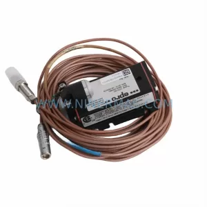
EPRO PR6423/10R-030 CON021 Service-Ready Spare Part
SKU: PR6424/012-000 CON011
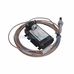
EPRO PR6424/012-000 CON011 Service-Ready Spare Part
Catalog Continuation
Alternative parts within TSI & Rotating Machinery Monitoring.
Stay inside the same system family when you need substitutes, adjacent modules, or a broader shortlist for procurement review.
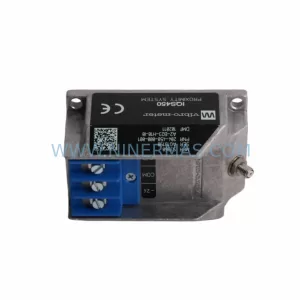
SKU: 204-900-000-011
Vibro-meter 204-900-000-011 Safety-Reliable Vibration Monitor
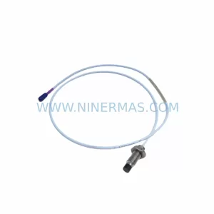
SKU: 330703-000-060-90-02-00
Bently Nevada 330703-000-060-90-02-00 Retrofit Module
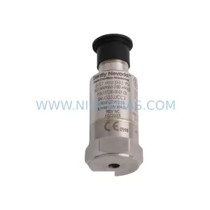
SKU: 177230-00-01-CN 16925-33
Bently Nevada 177230-00-01-CN 16925-33 Service-Ready Spare Part for Industrial Maintenance