Original Industrial Spare Part
DUPLOMATIC DDC4-30-230/20 Service-Ready Spare Part for Industrial Maintenance
Verify the part, confirm the platform family, and move straight into quotation with the right commercial details.
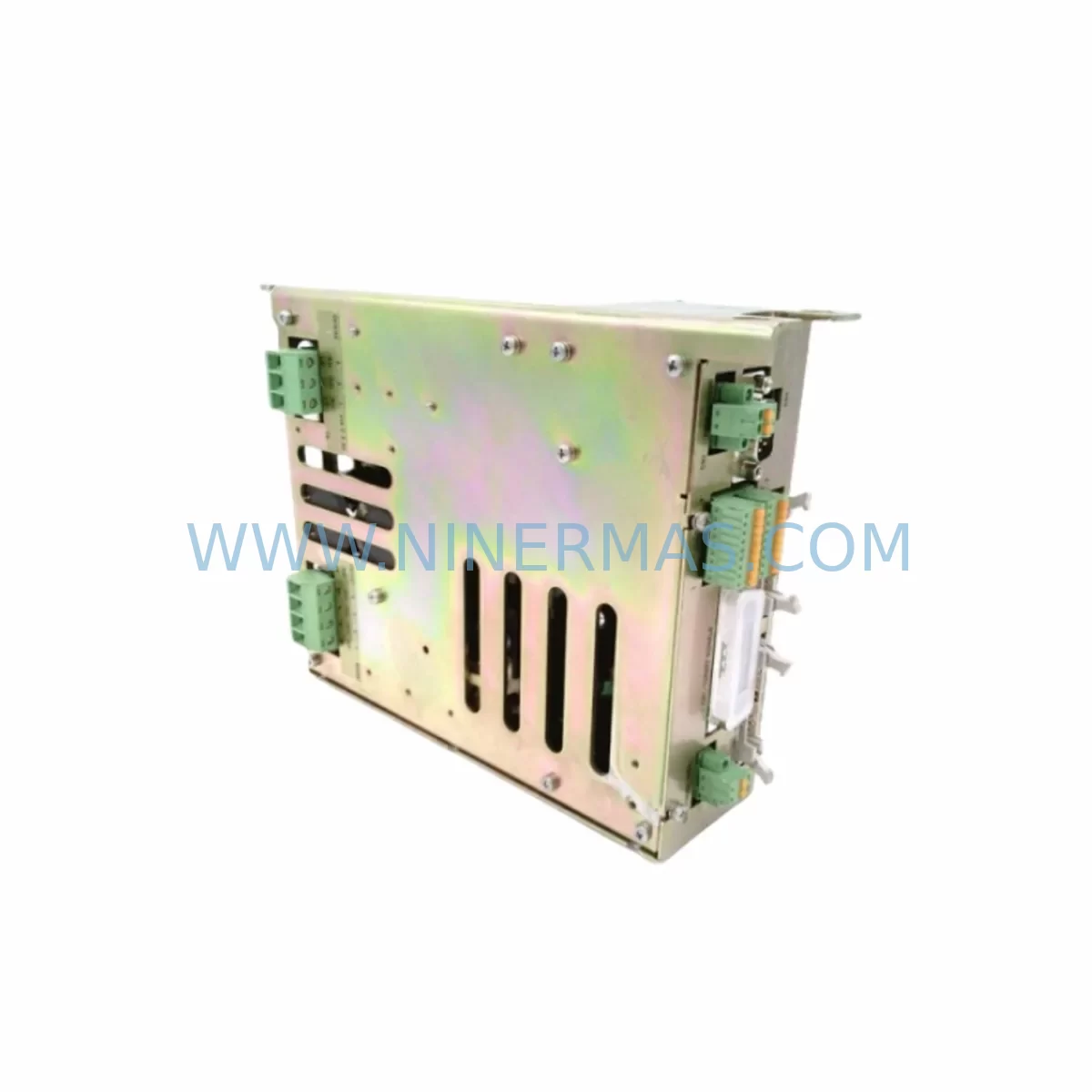
RFQ Ready
- SKUDDC4-30-230/20
- CategoryPLC & Industrial Automation Modules
- BrandDUPLOMATIC
- SupportAvailability, lead time, condition, and shipping coordination
How Buyers Usually Use This Page
- Confirm the exact part number and platform family before sending the quote request.
- Use direct email when quantity, condition, and destination are already defined internally.
- Switch to the broader brand or category archive when you need alternates nearby.
Series Navigation
Move through the most common platform families behind this part.
Product RFQ
Send this part directly for quotation.
Include quantity, required condition, destination country, and target delivery timing. Current reference: DUPLOMATIC DDC4-30-230/20 Service-Ready Spare Part for Industrial Maintenance with SKU DDC4-30-230/20.
DUPLOMATIC DDC4-30-230/20 Service-Ready Spare Part for Industrial Maintenance
The DUPLOMATIC DDC4-30-230/20 is a ruggedized servo drive module engineered for demanding industrial environments where continuous motion control reliability is non-negotiable. As a direct-replacement spare part, this unit is sourced to support maintenance engineers and procurement teams managing legacy hydraulic and electro-hydraulic servo systems. Whether you are responding to an unplanned shutdown, executing a scheduled annual overhaul, or building a strategic spare parts buffer, the DDC4-30-230/20 delivers the electrical performance and mechanical compatibility required to restore production with minimal downtime.
DUPLOMATIC’s DDC series servo drive modules are widely deployed in precision motion control applications including CNC machine tools, hydraulic press lines, injection moulding machines, and industrial test rigs. The DDC4-30-230/20 variant is rated for 230 V AC input with a 30 A continuous output current capacity, making it suitable for mid-to-high power servo axis applications. Its ruggedized design addresses vibration, thermal cycling, and EMI exposure typical of factory floor control cabinets.
Spare Maintenance Table
| SKU / Part Number | DDC4-30-230/20 |
| Brand / Manufacturer | DUPLOMATIC |
| Series | DDC4 |
| Product Type | Servo Drive Module |
| Input Voltage | 230 V AC (±10%), 50/60 Hz |
| Continuous Output Current | 30 A |
| Peak Output Current | ~60 A (estimated, per DDC4 series spec) |
| Control Interface | Analogue ±10 V / Enable signal / Fault relay |
| Feedback Compatibility | Resolver / Encoder (series-dependent) |
| Protection Class | Overcurrent, Overvoltage, Overtemperature, Short-circuit |
| Mounting | DIN rail / Panel mount (control cabinet) |
| Operating Temperature | 0 °C to +45 °C (derated above 40 °C) |
| Country of Origin | Italy |
| Application Environment | Industrial control cabinet, CNC, hydraulic press, test rig |
| Maintenance Recommendation | Replace cooling fan and inspect DC bus capacitors every 3–5 years; verify feedback cable shielding on installation |
| Warranty | 12 Months from shipment date |
| Pre-Shipment Testing | Yes — functional and electrical verification before dispatch |
Maintenance Planning for Continuous Operation
When a DDC4-30-230/20 servo drive fails or is flagged during a control cabinet inspection, experienced maintenance engineers know that the drive itself is rarely the only component requiring attention. A thorough site assessment should accompany every servo drive replacement to prevent repeat failures and ensure the restored axis performs within specification.
Begin by inspecting the 24 V DC auxiliary power supply feeding the drive’s control board — an unstable auxiliary rail is a common root cause of nuisance faults and drive lockouts. Check the three-phase AC input contactor and line reactor upstream of the drive; worn contactor contacts introduce voltage asymmetry that stresses the drive’s rectifier bridge. Verify the condition of the DC bus fuses or fast-blow semiconductor fuses protecting the inverter stage — these should be replaced as a matter of course during any drive swap.
On the feedback side, inspect the resolver or encoder cable for insulation damage, connector corrosion, and shield continuity. A degraded feedback signal is a leading cause of velocity loop instability and position error faults in DDC4-series drives. If the machine uses a DUPLOMATIC proportional valve amplifier card in the same hydraulic servo loop, confirm its reference signal and dither settings are compatible with the replacement drive’s output characteristics.
For systems integrated into a broader PLC or CNC architecture, review the I/O interface wiring between the drive’s enable, fault, and ready signals and the controller — particularly if the host controller is a SIEMENS SIMATIC S7 series, a FANUC Series 0i, or a Bosch Rexroth IndraControl platform. Confirm that the analogue reference signal cable (±10 V command) is properly shielded and routed away from power cables to avoid induced noise.
Where the DDC4-30-230/20 is installed in a multi-axis cabinet, also inspect the shared DC bus bar connections and bus capacitor bank for signs of electrolytic degradation. Alongside the drive replacement, it is good practice to audit the terminal blocks and cable ferrules on the power and signal wiring — loose terminations are a disproportionate source of intermittent faults in servo systems operating under vibration. Finally, if the cabinet houses a DUPLOMATIC DDC4 series companion axis drive of similar vintage, consider scheduling its inspection or replacement within the same maintenance window to avoid a second unplanned outage.
Site Replacement Workflow
Replacing the DDC4-30-230/20 on-site follows a structured sequence to minimise downtime and ensure system compatibility from first power-on:
1. Isolation and documentation: De-energise the cabinet, lock out / tag out (LOTO), and photograph all wiring connections, parameter labels, and DIP switch or potentiometer settings on the outgoing drive before disconnection.
2. Mechanical removal: Disconnect the AC input, motor power (U/V/W), DC bus, feedback cable, and control signal connectors in sequence. Remove the drive from its mounting rail or panel.
3. Parameter transfer: Record all gain settings, current limits, speed references, and fault thresholds from the outgoing drive’s documentation or from the machine’s commissioning records. The DDC4-30-230/20 replacement unit ships with factory defaults and must be configured to match the original axis parameters before enabling.
4. Installation and wiring: Mount the replacement unit, reconnect all cables following the original wiring diagram, and verify feedback cable shield grounding at the drive end only (single-point grounding).
5. Pre-enable checks: With the drive powered but the axis enable signal held low, verify auxiliary supply voltage, check for any pre-existing fault codes, and confirm the DC bus charges correctly through the pre-charge resistor circuit.
6. Commissioning: Enable the axis at low speed, verify feedback direction and velocity loop stability, then ramp to full operating speed. Confirm position accuracy and fault-free operation across the full duty cycle before returning the machine to production.
This workflow is compatible with legacy machine retrofits where the DDC4-30-230/20 replaces an older DUPLOMATIC DDC3 or DDC2 series drive, provided the motor feedback type and power rating are matched. Mechanical and electrical form-factor compatibility should be confirmed against the original machine documentation before ordering.
Spare Parts Support FAQ
Q1: Is the DDC4-30-230/20 still in production, and can I rely on long-term supply?
The DDC4 series is a mature product line. While DUPLOMATIC continues to support the series, availability of new units may be subject to lead times. We maintain dedicated stock of service-ready units to support maintenance teams requiring fast turnaround. Long-term supply continuity is a core part of our spare parts programme — contact us to discuss blanket order or consignment stock arrangements.
Q2: How do I verify compatibility before installing the replacement drive?
Confirm the input voltage (230 V AC), continuous current rating (30 A), and feedback interface type (resolver or encoder) against your machine’s electrical schematic and the nameplate of the outgoing drive. Cross-reference the DDC4-30-230/20 part number with the DUPLOMATIC documentation for your specific machine model. If you require compatibility confirmation support, our technical team can assist prior to shipment.
Q3: What does the 12-month warranty cover, and what pre-shipment testing is performed?
Every DDC4-30-230/20 unit is subject to functional and electrical verification testing before dispatch, including input/output power checks, feedback interface validation, and protection circuit confirmation. The 12-month warranty covers manufacturing defects and functional failures under normal operating conditions from the date of shipment. It does not cover damage resulting from incorrect installation, overvoltage events, or operation outside the rated environmental parameters.
Q4: What is the recommended spare parts inventory strategy for servo drive modules?
For critical production axes, a minimum of one cold-standby spare per drive type is recommended. For high-utilisation or single-point-of-failure axes, consider holding a warm-standby unit pre-configured with the correct parameters. Annual inspection of in-service drives — including thermal imaging of the heatsink, measurement of DC bus capacitor ESR, and review of fault log history — allows condition-based replacement before failure occurs, reducing unplanned downtime risk significantly.
| Product Series | Other series |
|---|
Catalog Continuation
Alternative parts within PLC & Industrial Automation Modules.
Stay inside the same system family when you need substitutes, adjacent modules, or a broader shortlist for procurement review.
SKU: 6ES5470-4UC12
Siemens 6ES5470-4UC12 Retrofit-Compatible Analog Output
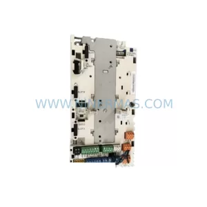
SKU: ZCU-12L 3AXD50000794058
ABB ZCU-12L 3AXD50000794058 Service-Ready Spare Part