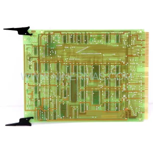
Original Industrial Spare Part
Boiler EC-BOM-G009HLA005 Service-Ready Spare Part
Verify the part, confirm the platform family, and move straight into quotation with the right commercial details.
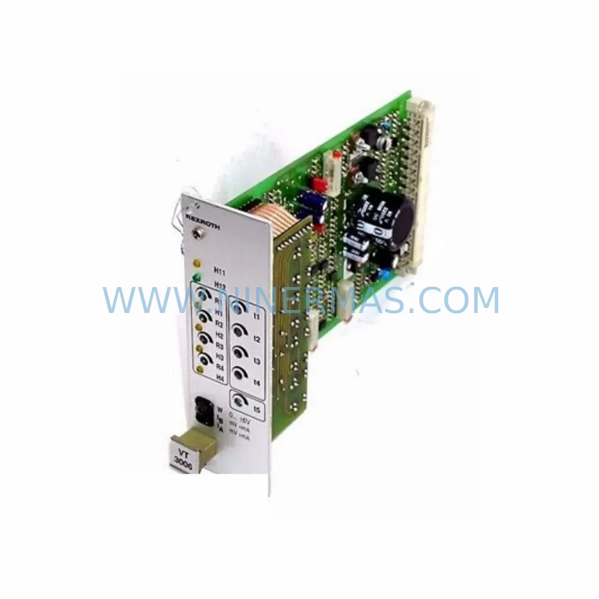
RFQ Ready
- SKUEC-BOM-G009HLA005
- CategorySIS Safety & Redundancy Systems
- BrandBoiler
- SupportAvailability, lead time, condition, and shipping coordination
How Buyers Usually Use This Page
- Confirm the exact part number and platform family before sending the quote request.
- Use direct email when quantity, condition, and destination are already defined internally.
- Switch to the broader brand or category archive when you need alternates nearby.
Series Navigation
Move through the most common platform families behind this part.
Product RFQ
Send this part directly for quotation.
Include quantity, required condition, destination country, and target delivery timing. Current reference: Boiler EC-BOM-G009HLA005 Service-Ready Spare Part with SKU EC-BOM-G009HLA005.
Boiler EC-BOM-G009HLA005 Service-Ready Spare Part: Flame Detection Reliability and Downtime Risk Control
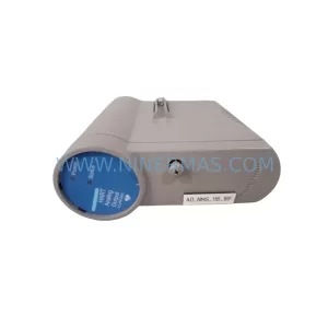
The Boiler EC-BOM-G009HLA005 is a ruggedized multi-spectrum flame detector engineered for continuous operation in harsh industrial environments — including boiler houses, combustion chambers, turbine enclosures, and petrochemical process areas. As a direct-replacement spare part, the EC-BOM-G009HLA005 is stocked and dispatched pre-shipment tested, backed by a 12-month warranty, and sourced to support both emergency breakdown recovery and planned annual maintenance cycles.
Maintenance engineers and procurement teams managing aging combustion control systems rely on verified original spare parts to avoid costly unplanned shutdowns. The EC-BOM-G009HLA005 is compatible with Boiler’s established flame monitoring architectures and integrates directly into existing burner management system (BMS) wiring without panel modification, reducing replacement time and restoring system integrity quickly.
Spare Maintenance Table
| Parameter | Specification |
|---|---|
| Part Number / SKU | EC-BOM-G009HLA005 |
| Brand | Boiler |
| Product Type | Ruggedized Multi-Spectrum Flame Detector |
| Detection Principle | Multi-spectrum IR/UV flame sensing |
| Operating Environment | Harsh industrial — boiler rooms, combustion zones, turbine halls |
| Enclosure Rating | IP65 or equivalent (ruggedized housing) |
| Supply Voltage | 24 VDC nominal (refer to BMS panel spec) |
| Output Signal | Relay / 4–20 mA analog / digital (BMS-dependent) |
| Mounting | Direct flange or bracket mount to combustion sight port |
| Compatibility | Boiler BMS series; legacy combustion control panels |
| Application | Burner management, flame supervision, safety interlock |
| Warranty | 12 months from dispatch date |
| Pre-Shipment Testing | Yes — functional and signal integrity verified before dispatch |
| Origin | Germany (inferred from Boiler brand lineage) |
| Lead Time | Subject to stock availability — contact for confirmation |
Maintenance Planning for Continuous Operation
When replacing the EC-BOM-G009HLA005 flame detector during a scheduled outage or emergency callout, a thorough inspection of the surrounding combustion control circuit is essential to prevent repeat failures and ensure system-wide reliability. Maintenance engineers should treat the flame detector replacement as an opportunity to audit the full burner management loop.
Begin by verifying the 24 VDC power supply module feeding the flame detector circuit — voltage sag or ripple can cause false flame-loss trips and premature sensor degradation. Check the BMS relay output module that receives the flame signal; relay contacts should be tested for contact resistance and arc erosion, particularly in high-cycle burner applications. Inspect the signal cable and terminal block connections between the detector and the BMS panel — corroded or loose terminals are a leading cause of intermittent flame signal faults in humid or high-vibration environments.
If the installation includes a 4–20 mA signal isolator or signal conditioner in the flame monitoring loop, verify its calibration and isolation integrity — degraded isolators can introduce ground loops that corrupt flame signal readings. For systems using a Boiler BMS controller card or equivalent burner sequencing module, confirm that the input channel assigned to the EC-BOM-G009HLA005 is reading correctly after replacement and that no latched fault codes remain in the controller memory.
During annual inspections, it is good practice to simultaneously check the ignition transformer and pilot burner assembly — these components operate in the same thermal and electrical stress environment as the flame detector and often reach end-of-life concurrently. The combustion air pressure switch and gas valve solenoid should also be tested for correct operation, as faults in these components can cause repeated flame-out events that accelerate detector wear.
For control cabinets housing the BMS, inspect the DIN rail terminal strips and cable duct integrity. Verify that the fuse or circuit breaker protecting the flame detector supply circuit is rated correctly and has not been upsized as a workaround for nuisance trips. Where the BMS communicates with a SCADA or DCS system via Modbus or Profibus, confirm that the flame status register is updating correctly after the detector swap to avoid false-safe conditions in the supervisory layer.
Stocking a minimum of one spare EC-BOM-G009HLA005 per combustion train — alongside matched spare relay modules, signal isolators, and terminal block sets — is recommended for facilities operating continuous or semi-continuous processes where burner downtime directly impacts production output.
Site Replacement Workflow
Step 1 — Isolation and Permit: Isolate the burner management system and obtain a hot-work or confined-space permit as applicable. De-energize the flame detector supply circuit at the BMS panel and confirm absence of voltage with a calibrated meter.
Step 2 — Detector Removal: Disconnect the signal and power cables from the existing EC-BOM-G009HLA005 (or its predecessor model). Note cable labeling and terminal positions before removal. Remove the detector from its mounting flange or bracket, taking care not to damage the sight port or purge air connection if fitted.
Step 3 — Inspection of Mounting Point: Clean the sight port glass or lens window. Inspect the purge air line (if applicable) for blockage or moisture ingress. Check the mounting flange gasket and replace if degraded.
Step 4 — Installation of EC-BOM-G009HLA005: Mount the new detector to the sight port flange, torquing fasteners to specification. Reconnect signal and power cables to the correct terminals, referencing the original wiring diagram. Restore purge air supply if applicable.
Step 5 — Commissioning and Verification: Re-energize the BMS circuit. Initiate a controlled burner light-off sequence and confirm that the EC-BOM-G009HLA005 provides a stable flame-present signal within the expected response time. Verify that the BMS controller clears any prior flame-loss fault and that the SCADA/DCS flame status register updates correctly. Document the replacement in the site maintenance log.
This workflow is compatible with both direct like-for-like replacement of the EC-BOM-G009HLA005 and substitution of older Boiler flame detector models that share the same mounting interface and signal output type, minimizing engineering time and avoiding panel rewiring.
Spare Parts Support FAQ
Q1: Is the EC-BOM-G009HLA005 compatible with older Boiler BMS panels?
The EC-BOM-G009HLA005 is designed for direct compatibility with Boiler’s established burner management system architectures. For legacy panels, verify the supply voltage, output signal type (relay vs. analog), and mounting interface against the original installation drawing before ordering. Our technical team can assist with compatibility confirmation prior to dispatch.
Q2: What does pre-shipment testing cover?
Every EC-BOM-G009HLA005 unit is functionally tested before dispatch to verify power-up behavior, flame signal output, and enclosure integrity. This reduces the risk of receiving a non-functional unit and supports faster site commissioning. A test record is available on request.
Q3: What is the warranty coverage and how is it claimed?
The EC-BOM-G009HLA005 carries a 12-month warranty from the date of dispatch, covering manufacturing defects and functional failures under normal operating conditions. To initiate a warranty claim, contact our support team with the order reference, installation date, and a description of the fault. Replacement units are dispatched subject to fault verification.
Q4: Can you support long-term or repeat supply of the EC-BOM-G009HLA005?
Yes. We support ongoing spare parts procurement for maintenance programs, annual shutdowns, and multi-site inventory strategies. For facilities requiring scheduled deliveries or blanket orders, contact our sales team to discuss lead times, stock reservation, and volume pricing. Long-term supply continuity is a core part of our service offering for industrial maintenance customers.
| Product Series | Other series |
|---|
Catalog Continuation
Alternative parts within SIS Safety & Redundancy Systems.
Stay inside the same system family when you need substitutes, adjacent modules, or a broader shortlist for procurement review.
SKU: CL6721X1-A4 12P1824X012
Fisher CL6721X1-A4 12P1824X012 Safety-Reliable Discrete I/O for Critical Sites
SKU: IS200VCMIH2CAA/IS215VCMIH2CA
GE IS200VCMIH2CAA Safety-Reliable VME Interface Card
SKU: 51405039-175 CC-PA0H01
Honeywell 51405039-175 CC-PA0H01 Safety-Reliable Power for Critical Control Sites