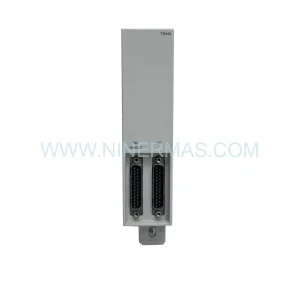
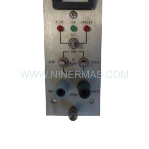
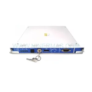
Original Industrial Spare Part
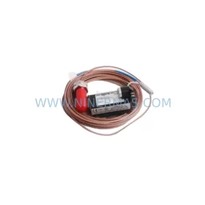
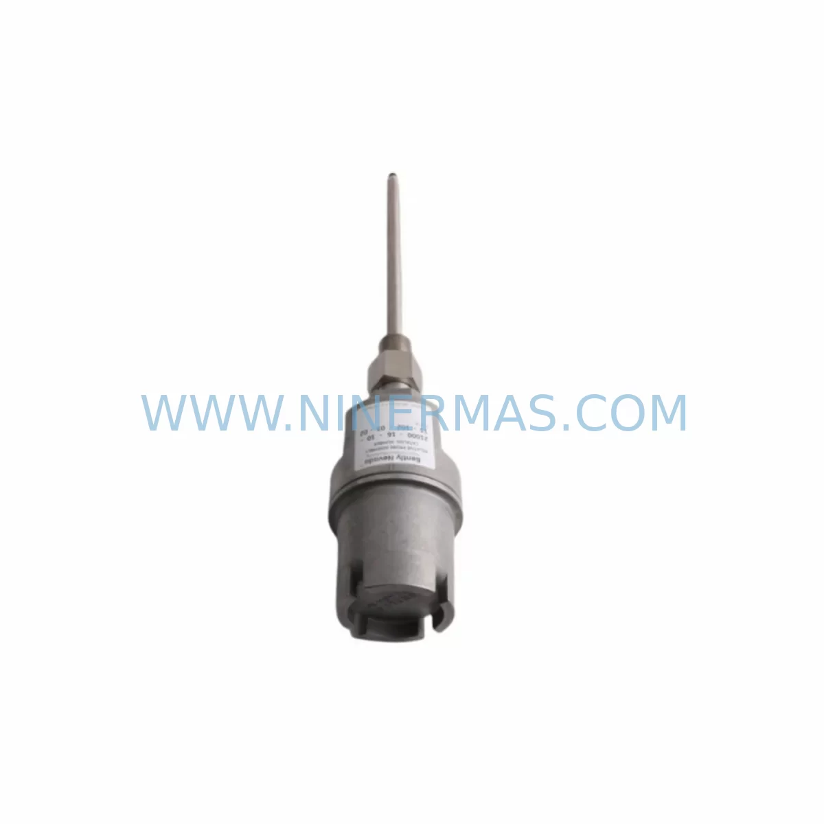
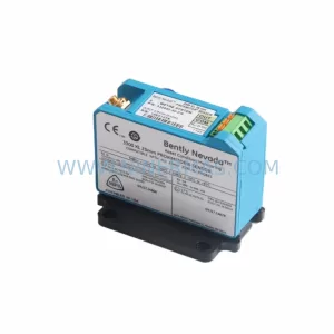
Bently Nevada 21000-28-05-35-028-00-02 Retrofit Proximity Probe
Verify the part, confirm the platform family, and move straight into quotation with the right commercial details.
RFQ Ready
- SKU21000-28-05-35-028-00-02
- CategoryTSI & Rotating Machinery Monitoring
- BrandBently Nevada
- SupportAvailability, lead time, condition, and shipping coordination
How Buyers Usually Use This Page
- Confirm the exact part number and platform family before sending the quote request.
- Use direct email when quantity, condition, and destination are already defined internally.
- Switch to the broader brand or category archive when you need alternates nearby.
Series Navigation
Move through the most common platform families behind this part.
Product RFQ
Send this part directly for quotation.
Include quantity, required condition, destination country, and target delivery timing. Current reference: Bently Nevada 21000-28-05-35-028-00-02 Retrofit Proximity Probe with SKU 21000-28-05-35-028-00-02.
Bently Nevada 21000-28-05-35-028-00-02 Retrofit-Compatible Proximity Probe Housing for Legacy Systems
The Bently Nevada 21000-28-05-35-028-00-02 is a precision-engineered proximity probe housing assembly designed for seamless integration into aging industrial automation infrastructures. As legacy Bently Nevada 3300 Series and 7200 Series vibration monitoring systems approach end-of-life, plant engineers and maintenance teams face the critical challenge of sourcing verified replacement components that maintain signal integrity, dimensional compatibility, and system certification without triggering full-platform overhauls. This SKU addresses exactly that need — providing a retrofit-ready housing solution that preserves existing wiring layouts, probe tip geometry, and extension cable termination standards.
Whether you are managing a turbine protection system, compressor train monitoring rack, or a multi-channel vibration analysis cabinet, the 21000-28-05-35-028-00-02 housing assembly is engineered to slot into existing probe mounting positions with minimal mechanical modification. The housing maintains the standard 5-metre and 9-metre cable configurations common across the 21000 Series probe family, ensuring that field technicians do not need to re-route conduit or re-terminate junction boxes during the replacement procedure.
Upgrade Compatibility Table
| Parameter | Legacy Reference | 21000-28-05-35-028-00-02 Specification | Retrofit Note |
|---|---|---|---|
| Probe Series | 3300 XL / 7200 Series | 21000 Series | Direct housing swap; verify tip gap per OEM spec |
| Thread Size | M10 × 1.0 (standard) | M10 × 1.0 | No adapter required for standard mounting bosses |
| Cable Length | 5 m / 9 m | 5 m (28-05 suffix) | Confirm extension cable 330130-045-00-CN compatibility |
| Driver Compatibility | 3300 RAM / 3500/25 Monitor | Compatible with 3500/25, 3500/40M, 3500/42M | Verify driver gap voltage range: −10 VDC nominal |
| Communication Protocol | Analogue 4–20 mA / Keyphasor | Analogue output; Keyphasor reference supported | No protocol migration required |
| Installation Space | Standard probe boss, 22 mm clearance | 22 mm minimum radial clearance | Confirm bearing housing access before installation |
| Rack / Backplane | 3500 Rack (19-inch) | No rack change required | Housing is field-mounted; rack unchanged |
| Warranty | — | 12-Month Warranty | Covers manufacturing defects and signal performance |
Retrofit Planning for Existing Automation Systems
Successful integration of the 21000-28-05-35-028-00-02 into a running plant begins well before the physical swap. A structured retrofit plan must account for the full signal chain — from the probe tip through the extension cable, into the driver, and ultimately to the monitor module seated in the 3500 Rack. When replacing a worn or discontinued housing assembly, the first step is to verify that the existing Bently Nevada 330130-045-00-CN extension cable is undamaged and within its calibrated length tolerance. A mismatched cable length will shift the driver’s linear range and produce erroneous gap voltage readings at the 3500/25 Proximitor Monitor or 3500/40M Proximitor I/O Module.
Power supply integrity is equally critical. The 3500 Power Supply module — typically a 3500/15 or 3500/05 — must deliver stable −24 VDC to the driver circuit. Before removing the legacy probe housing, technicians should confirm that the rack power supply is within specification using a calibrated multimeter at the terminal block. If the power supply is approaching end-of-life, this retrofit window is an ideal opportunity to simultaneously replace it, avoiding a secondary unplanned outage weeks later.
Terminal wiring at the I/O module must be documented before disconnection. The 3500/42M Proximitor I/O Module uses a standard 25-pin D-sub field wiring connector, and each channel’s shield drain wire must be re-terminated correctly to prevent ground loop interference after the new housing is installed. Technicians should photograph or sketch the existing wiring layout and cross-reference it against the channel assignment in the System 1 configuration database or the 3500 Rack Configuration Software before proceeding.
For plants running Bently Nevada System 1 Evolution software, the probe channel configuration — including full-scale range, alert setpoints, danger setpoints, and Keyphasor association — is stored in the software database and does not need to be re-entered after a like-for-like housing replacement. However, if the replacement involves a change in probe sensitivity (e.g., moving from a 7.87 V/mm to a 7.87 V/mm driver pair), the System 1 channel scaling must be reviewed and confirmed. The 3500/22M Transient Data Interface module, if present in the rack, should also be checked to ensure its sampling configuration remains aligned with the new probe’s output characteristics.
In multi-machine installations where the 21000 Series probes are used alongside Bently Nevada 3300 XL 8mm Proximity Transducer Systems, it is common to find mixed probe generations within the same control cabinet. Retrofit planning should include a rack-level audit to identify which channels are sourced from legacy 3300 XL housings and which are already on the 21000 Series platform. This audit prevents accidental cross-channel configuration errors during the commissioning phase. The Bently Nevada 3500/20 Rack Interface Module provides the communication bridge to the plant DCS or safety system, and its configuration should be backed up before any rack-level work begins.
Where HMI screens in the control room display vibration trend data sourced from these probe channels, the HMI tag mapping should be verified post-installation. Systems running on GE iFIX, Wonderware InTouch, or Rockwell FactoryTalk View SE may require a tag refresh or OPC server reconnection if the 3500 Rack’s Modbus TCP or OPC DA configuration was temporarily interrupted during the retrofit. Confirming HMI display continuity before returning the machine to service is a mandatory step in the site acceptance test protocol.
Downtime Control During System Migration
Minimising production downtime during a proximity probe housing replacement requires a disciplined pre-outage preparation process. All replacement components — including the 21000-28-05-35-028-00-02 housing, the matched extension cable, and any required armoured conduit fittings — should be staged and inspected at the work site before the machine is taken offline. A pre-tested spare assembly, verified on a bench driver simulator against a known gap voltage curve, eliminates the risk of discovering a defective component after the machine is already shut down.
The original probe program logic and setpoint configuration stored in the 3500 Rack should be exported and saved to a secure backup location before the outage begins. This protects against accidental parameter loss if a rack module is inadvertently reset during the physical work. The backup file should include the full rack configuration, channel assignments, alert and danger thresholds, and any custom Keyphasor-based speed calculation parameters.
During the physical replacement, the machine’s vibration monitoring channels should be placed in bypass mode through the 3500 Rack’s front-panel interface or through System 1, preventing spurious danger trips while the probe is disconnected. Once the new 21000-28-05-35-028-00-02 housing is installed and the extension cable is reconnected, the gap voltage should be measured and adjusted to the target value — typically −10.0 VDC ± 0.5 VDC — before the bypass is removed. This single verification step is the most effective way to confirm correct installation before the machine is restarted.
Post-installation, a short observation period of 15 to 30 minutes at reduced load allows the vibration trend data to stabilise and confirms that the new probe housing is tracking shaft movement correctly. Any deviation from the pre-outage baseline trend should be investigated before returning the machine to full load. Documenting the as-found and as-left gap voltages, along with the installation date and technician sign-off, creates a traceable maintenance record that supports future reliability analysis and spare parts lifecycle planning.
Retrofit Support FAQ
Q1: Is the 21000-28-05-35-028-00-02 a direct replacement for discontinued 3300 XL proximity probe housings?
The 21000-28-05-35-028-00-02 is designed as a retrofit-compatible replacement for legacy Bently Nevada proximity probe housings used in 3300 XL and early 7200 Series applications. Thread dimensions, cable termination style, and driver compatibility are maintained. A gap voltage verification is required after installation to confirm correct positioning within the driver’s linear range.
Q2: What commissioning steps are required after installing this housing?
After mechanical installation, measure the gap voltage at the driver output terminal using a calibrated multimeter. Adjust the probe tip-to-target gap until the voltage reads within the specified linear range (typically −10.0 VDC ± 0.5 VDC for standard 5-metre systems). Remove the channel bypass in the 3500 Rack, confirm the vibration reading in System 1 or the local HMI, and document the as-left gap voltage in the maintenance record.
Q3: Can this housing be used with existing extension cables and drivers already installed in the field?
Yes, provided the existing extension cable is the correct length and is undamaged. The 21000 Series housing is calibrated as a system with its matched driver and extension cable. If the extension cable is being reused from a legacy installation, confirm that its length matches the 28-05 (5-metre) designation of this SKU. Mixing cable lengths from different system configurations will affect the driver’s output linearity and must be avoided.
Q4: What does the 12-month warranty cover, and is pre-shipment testing performed?
Every 21000-28-05-35-028-00-02 unit is subject to pre-shipment functional testing, including gap voltage linearity verification and housing integrity inspection, before dispatch. The 12-month warranty covers manufacturing defects, signal performance deviations, and housing assembly failures under normal operating conditions. Warranty claims are supported by NINERMAS COMPANY LIMITED with direct technical assistance. Contact sale@ninermas.com or +0086 187 5021 5667 for warranty registration and support.
| Product Series | 21000 Series |
|---|---|
| Country of Origin | US |
Catalog Continuation
More Bently Nevada modules in the catalog.
Use the brand lane to compare nearby part numbers, platform-adjacent modules, and other inquiry-ready listings before sending your final RFQ.
SKU: 330194-13-20-10-00
Bently Nevada 330194-13-20-10-00 Safety-Reliable Monitor for Critical Control
SKU: 330701-00-40-10-11-05
Bently Nevada 330701-00-40-10-11-05 Safety Vibration Monitor
SKU: 21000-33-05-00-035-03-02
Bently Nevada 21000-33-05-00-035-03-02 Safety Relay
Catalog Continuation
Alternative parts within TSI & Rotating Machinery Monitoring.
Stay inside the same system family when you need substitutes, adjacent modules, or a broader shortlist for procurement review.