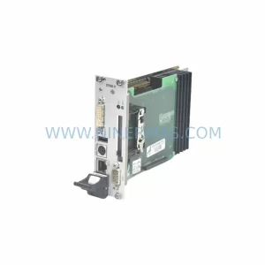
Original Industrial Spare Part
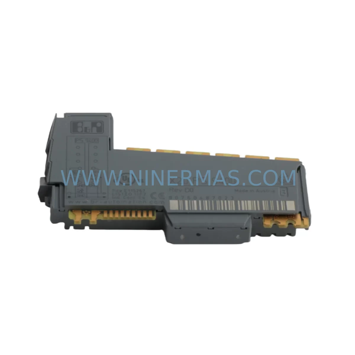
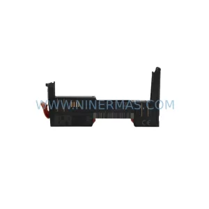
B&R X20PS9400 Service-Ready Spare Part for Industrial Maintenance
Verify the part, confirm the platform family, and move straight into quotation with the right commercial details.
RFQ Ready
- SKUX20PS9400
- CategoryPLC & Industrial Automation Modules
- BrandB&R
- SupportAvailability, lead time, condition, and shipping coordination
How Buyers Usually Use This Page
- Confirm the exact part number and platform family before sending the quote request.
- Use direct email when quantity, condition, and destination are already defined internally.
- Switch to the broader brand or category archive when you need alternates nearby.
Series Navigation
Move through the most common platform families behind this part.
Product RFQ
Send this part directly for quotation.
Include quantity, required condition, destination country, and target delivery timing. Current reference: B&R X20PS9400 Service-Ready Spare Part for Industrial Maintenance with SKU X20PS9400.
B&R X20PS9400 Service-Ready Spare Part for Industrial Maintenance
The B&R X20PS9400 is a ruggedized power supply module engineered for the X20 modular PLC platform — one of the most widely deployed automation architectures in process manufacturing, machine building, and critical infrastructure. When an X20PS9400 fails or reaches end-of-service life, the downstream impact is immediate: the entire X20 backplane loses regulated DC power, halting I/O scanning, CPU execution, and fieldbus communication simultaneously. Sourcing a verified, pre-tested replacement unit is the single fastest path to restoring production uptime.
At NINERMAS, every X20PS9400 unit is subject to pre-shipment functional verification — output voltage stability, inrush current behavior, and thermal performance are confirmed before dispatch. Each unit ships with a 12-month warranty covering manufacturing defects and functional failure under normal operating conditions. Our inventory is maintained specifically to support maintenance engineers and procurement teams who cannot afford extended lead times on critical automation components.
Spare Maintenance Table
| Parameter | Specification / Detail |
|---|---|
| Part Number / SKU | X20PS9400 |
| Brand | B&R (Bernecker + Rainer) |
| Series | X20 Modular PLC System |
| Module Type | Power Supply Module (Backplane Power Feed) |
| Nominal Input Voltage | 24 VDC (SELV/PELV compliant) |
| Output / Bus Supply | Regulated internal X2X Link bus power |
| Protection Class | IP20 (panel-mount, control cabinet installation) |
| Operating Temperature | 0 °C to +55 °C (storage: −25 °C to +70 °C) |
| Mounting | DIN rail, snap-fit onto X20 backplane |
| Compatibility | B&R X20 series backplanes, X20 CPU modules, X20 I/O modules |
| Application Environment | Industrial automation, machine control, process manufacturing, harsh environments |
| Certifications | CE, UL (per B&R standard X20 platform approvals) |
| Maintenance Recommendation | Replace at first sign of voltage instability, module fault LED, or X2X bus dropout |
| Warranty | 12 Months — covers manufacturing defects and functional failure |
| Pre-Shipment Test | Yes — output voltage, inrush current, and thermal performance verified |
| Origin | Austria (B&R headquarters; Eggelsberg) |
| Availability | In-stock; ready for immediate dispatch |
Maintenance Planning for Continuous Operation
A power supply module failure in an X20 system rarely occurs in isolation. The X20PS9400 feeds regulated bus voltage to every module seated on the same backplane segment — meaning a degraded or failed unit can produce cascading faults across the X20CP1485 or X20CP3485 CPU module, all downstream X20DI digital input modules, X20DO digital output modules, and any X20AI analog input modules sharing that bus segment. Maintenance engineers responding to an X20PS9400 fault should treat the event as a full backplane health review, not a single-component swap.
Begin by verifying the 24 VDC supply rail feeding the X20PS9400 input terminals. A failing upstream industrial DIN rail power supply (such as a 24 VDC SITOP or equivalent) is a common root cause of repeated power module faults. Check input voltage under load — not just at idle — and inspect the terminal block wiring and cable ferrules at the power feed connection for oxidation, loose crimps, or thermal discoloration.
Once the X20PS9400 is replaced, inspect the X20BM backplane bus module for physical damage or connector wear, as repeated module insertions in high-vibration environments can degrade the backplane contacts. If the system includes X20IF fieldbus interface modules — PROFIBUS, PROFINET, or EtherNet/IP — verify that communication is fully restored after the power cycle, as some fieldbus masters require a manual re-initialization following an unplanned bus dropout.
For systems operating in environments with significant electrical noise, review the installation of signal isolators or galvanic isolation modules on analog I/O channels. Voltage transients that damage power supply modules often also degrade analog signal conditioning components. Similarly, inspect any X20 safety modules (SIL-rated I/O) for latched fault states that may not self-clear after power restoration.
Procurement engineers building a spare parts kit around the X20PS9400 should also stock at least one spare X20 CPU module of the installed variant, a set of X20 I/O modules matching the most critical process signals, and a spare 24 VDC DIN rail power supply sized for the full backplane load. Maintaining these components on-site reduces mean time to repair (MTTR) from days to hours in the event of a compound failure.
Site Replacement Workflow
Step 1 — Isolate and document. Before removing the X20PS9400, record the current system state: note any active fault codes on the B&R Automation Studio project or connected HMI panel, capture a screenshot of the I/O status, and confirm the 24 VDC input is de-energized at the upstream circuit breaker or fuse terminal.
Step 2 — Remove the faulty module. Disengage the DIN rail locking tab and slide the X20PS9400 off the backplane. Inspect the backplane connector pins for debris or deformation before installing the replacement unit.
Step 3 — Install the replacement X20PS9400. Seat the new module firmly onto the backplane until the connector engages fully. Re-engage the DIN rail lock. Reconnect the 24 VDC input wiring, verifying polarity and terminal torque to the manufacturer’s specification.
Step 4 — Power-up and verify. Restore 24 VDC input power. Confirm the module status LED indicates normal operation (green, no fault). Verify that the X2X bus link is active and that all downstream I/O modules have returned to their configured states. Check the CPU module for any residual fault flags and clear them via Automation Studio or the HMI if required.
Step 5 — Functional test before returning to production. Execute a controlled I/O scan — activate each digital output channel individually and verify the corresponding field device response. For analog channels, apply a known reference signal and confirm the engineering unit reading at the HMI. Only return the system to automatic production mode after all channels pass functional verification.
This workflow is compatible with both hot-standby and single-CPU X20 configurations. For redundant systems, coordinate the replacement with the standby CPU switchover procedure to maintain uninterrupted process control during the maintenance window.
Spare Parts Support FAQ
Q1: Is the X20PS9400 a direct drop-in replacement for the unit currently installed in my X20 backplane?
Yes. The X20PS9400 is a standard X20 platform power supply module with a fixed mechanical and electrical interface. It is compatible with all X20 backplane variants that accept a power supply module in the designated slot. No firmware configuration is required for the power supply module itself — the CPU and I/O modules retain their configuration in non-volatile memory and resume normal operation after the power cycle.
Q2: What is the recommended spare parts stocking strategy for X20PS9400 in a multi-line facility?
For facilities operating three or more X20-based control panels, we recommend maintaining a minimum of two X20PS9400 units in on-site inventory. Power supply modules are high-stress components subject to capacitor aging and thermal cycling. A two-unit buffer ensures that a second failure can be addressed immediately while the first replacement unit is being replenished. For critical 24/7 production lines, consider a three-unit buffer with annual rotation to prevent shelf-aging of electrolytic components.
Q3: How do I verify compatibility before ordering if I am unsure of the exact backplane variant installed?
The X20PS9400 part number is printed on the module label. Cross-reference this against the B&R hardware configuration in Automation Studio (Hardware Configuration view) or the panel wiring diagram. If the installed module label is damaged or missing, the backplane type can be identified by the number of module slots and the X2X bus connector style. Contact our technical team at sale@ninermas.com with your panel photos or Automation Studio hardware tree export and we will confirm compatibility before shipment.
Q4: What does the 12-month warranty cover, and what is the process if a unit fails after installation?
The 12-month warranty covers manufacturing defects and functional failure under normal operating conditions — defined as installation within the specified voltage, temperature, and environmental ratings. It does not cover damage caused by incorrect wiring polarity, overvoltage events, or physical impact. If a unit fails within the warranty period, contact sale@ninermas.com with the order reference and a description of the failure mode. We will arrange a replacement dispatch or technical review within 3 business days. All warranty claims are handled directly without requiring return of the faulty unit in most cases, subject to failure description review.
| Product Series | Other series |
|---|---|
| Country of Origin | AT |
Catalog Continuation
More B&R modules in the catalog.
Use the brand lane to compare nearby part numbers, platform-adjacent modules, and other inquiry-ready listings before sending your final RFQ.
SKU: 8BVI0220HCD8.000-1
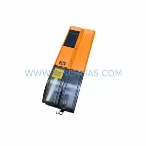
B&R 8BVI0220HCD8.000-1 Retrofit-Compatible Servo Drive for Legacy Systems
SKU: 5PC910.SX05-00
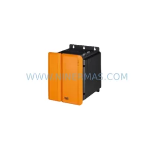
B&R 5PC910.SX05-00 Retrofit Industrial PC for Legacy Systems
Catalog Continuation
Alternative parts within PLC & Industrial Automation Modules.
Stay inside the same system family when you need substitutes, adjacent modules, or a broader shortlist for procurement review.