Original Industrial Spare Part
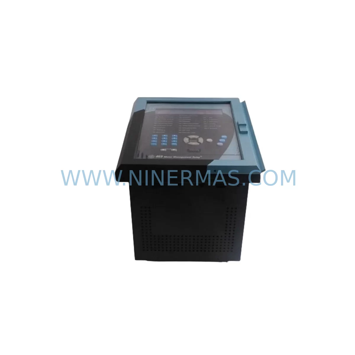
GE Multilin SR750-P5-G5-D5-HI-A1-R Service-Ready Spare Part
Verify the part, confirm the platform family, and move straight into quotation with the right commercial details.
RFQ Ready
- SKUSR750-P5-G5-D5-HI-A1-R
- CategorySIS Safety & Redundancy Systems
- BrandGE Multilin
- SupportAvailability, lead time, condition, and shipping coordination
How Buyers Usually Use This Page
- Confirm the exact part number and platform family before sending the quote request.
- Use direct email when quantity, condition, and destination are already defined internally.
- Switch to the broader brand or category archive when you need alternates nearby.
Series Navigation
Move through the most common platform families behind this part.
Product RFQ
Send this part directly for quotation.
Include quantity, required condition, destination country, and target delivery timing. Current reference: GE Multilin SR750-P5-G5-D5-HI-A1-R Service-Ready Spare Part with SKU SR750-P5-G5-D5-HI-A1-R.
GE Multilin SR750-P5-G5-D5-HI-A1-R Service-Ready Spare Part: Feeder Protection Relay for Industrial Maintenance and Downtime Recovery
The GE Multilin SR750-P5-G5-D5-HI-A1-R is a service-ready feeder protection relay designed for medium-voltage feeder and motor protection applications in industrial power distribution systems. As a direct replacement spare part for the SR750 series, this unit supports maintenance engineers and procurement teams managing aging control infrastructure, planned annual shutdowns, and emergency fault recovery scenarios where minimizing unplanned downtime is critical.
The SR750-P5-G5-D5-HI-A1-R variant is configured with a specific combination of power supply, I/O, and communication options that make it a precise fit for existing SR750 panel installations. When sourcing this relay as a spare, it is essential to verify the full model suffix against the installed unit’s nameplate to confirm compatibility with the existing wiring harness, CT/VT ratios, and protection setting files stored in the relay’s non-volatile memory.
Maintenance teams operating in utilities, petrochemical plants, water treatment facilities, mining operations, and heavy manufacturing environments rely on the SR750 series for overcurrent, earth fault, negative sequence, and thermal overload protection. A failed or degraded SR750-P5-G5-D5-HI-A1-R relay can expose an entire feeder circuit to unprotected fault conditions, making rapid spare availability a non-negotiable element of any electrical maintenance program.
Spare Maintenance Table
| Parameter | Specification / Detail |
|---|---|
| SKU / Model | SR750-P5-G5-D5-HI-A1-R |
| Brand | GE Multilin (Grid Solutions) |
| Series | SR750 Feeder Protection System |
| Product Type | Feeder Protection Relay |
| Primary Functions | Overcurrent, Earth Fault, Negative Sequence, Thermal Overload, Reclosing |
| Power Supply Option (P5) | 85–265 VAC / 88–300 VDC universal power supply |
| I/O Configuration (G5/D5) | Analog and digital I/O expansion for feeder monitoring and control |
| Communication (HI) | IEC 61850 / DNP3 / Modbus RTU — high-speed Ethernet port |
| Output Relay Option (A1) | Standard output relay configuration for trip and alarm circuits |
| Reclosing Option (R) | Integrated single/multi-shot reclosing logic |
| Mounting | Standard 19″ rack or panel flush mount |
| Operating Temperature | -40°C to +60°C |
| Application Environment | Utility substations, industrial MV switchgear, motor control centers |
| Compatibility | Direct replacement for SR750 series installations; settings-file compatible |
| Origin | Canada (GE Multilin manufacturing) |
| Warranty | 12 Months — covers manufacturing defects and functional failure |
| Pre-Shipment Testing | Yes — functional verification performed before dispatch |
| Condition | New / Service-Ready |
Maintenance Planning for Continuous Operation
When replacing the SR750-P5-G5-D5-HI-A1-R in the field, a thorough inspection of the surrounding electrical environment is essential to prevent repeat failures and ensure the new relay operates within its rated parameters from the first energization cycle.
Begin with the auxiliary power supply circuit. The SR750’s universal power supply input (P5 option) accepts a wide voltage range, but upstream fusing and surge suppression components should be inspected. Replace any blown or degraded DIN-rail mounted fuse holders and 2A control fuses that protect the relay’s DC/AC supply terminals. Verify that the 24VDC or 125VDC station battery supplying the relay is within tolerance and that the battery charger module is functioning correctly — a weak station battery is a common root cause of relay brownout events that can corrupt settings memory.
Inspect all CT (current transformer) secondary wiring connected to the relay’s current input terminals. Loose or corroded CT shorting links and terminal block connections on Phoenix Contact or Weidmuller terminal strips can introduce measurement errors that trigger nuisance trips or mask genuine fault conditions. If the CT secondary wiring shows signs of insulation degradation, replace the affected multi-conductor shielded control cables before commissioning the new relay.
For installations using the HI communication option, verify the integrity of the Ethernet patch cable or fiber optic SFP module connecting the SR750 to the substation LAN or SCADA system. A faulty communication link will prevent remote settings upload and event log retrieval, complicating post-fault analysis. Check the managed Ethernet switch port assigned to the relay and confirm VLAN configuration is preserved.
Review the status of adjacent protection and control components sharing the same switchgear panel. The SR469 motor protection relay or SR489 generator protection relay installed in the same lineup may share common DC bus wiring and should be inspected for similar aging symptoms. If the panel also contains a GE Multilin 350 feeder protection relay as a backup or bus protection device, confirm its settings are consistent with the SR750’s coordination curve.
Output relay wiring to trip coils, lockout relays (86 devices), and alarm annunciators must be continuity-tested before the new SR750-P5-G5-D5-HI-A1-R is energized. A failed trip coil or a seized lockout relay will prevent the protection system from clearing a fault even when the relay operates correctly. Similarly, inspect any interposing relay modules in the trip circuit for contact wear or coil resistance drift.
For sites using DNP3 or IEC 61850 GOOSE messaging, coordinate with the control room team to restore the relay’s IED configuration file (ICD/CID) from the engineering workstation backup. Uploading the correct settings file immediately after hardware replacement eliminates the risk of operating the feeder with default factory protection settings, which are not coordinated with the site’s protection scheme.
Procurement engineers should consider maintaining a minimum of one SR750-P5-G5-D5-HI-A1-R unit in the site spare parts store, particularly for installations where the SR750 series is the primary feeder protection platform across multiple bays. Pairing this relay spare with a set of pre-configured CT shorting plugs, spare output relay modules, and a licensed copy of the EnerVista SR750 Setup software ensures that field technicians can complete a full relay replacement and recommissioning within a single maintenance window.
Site Replacement Workflow
Step 1 — Isolation and De-energization: Follow the site’s switching program to isolate the feeder circuit. Open the circuit breaker, apply earthing, and verify absence of voltage on all phases. Isolate the relay’s auxiliary power supply and short all CT secondary circuits before disconnecting wiring.
Step 2 — Settings Backup: If the existing SR750-P5-G5-D5-HI-A1-R is still partially functional, connect a laptop running EnerVista SR750 Setup software via the front RS232 or rear Ethernet port and export the full settings file (.sr7 format). Store this file on a secure engineering server as the baseline for the replacement unit.
Step 3 — Hardware Removal: Label all wiring before disconnection. Remove the relay from the panel cutout, noting the orientation of the rear terminal blocks. The SR750 uses a drawout or fixed-mount chassis depending on the panel design — confirm the replacement unit matches the installed chassis type.
Step 4 — Replacement Installation: Mount the new SR750-P5-G5-D5-HI-A1-R, reconnect all wiring per the original schematic, and verify CT polarity and VT phase rotation before removing CT shorting links. Restore auxiliary power and confirm the relay powers up without alarm.
Step 5 — Settings Upload and Commissioning: Upload the saved settings file via EnerVista software. Perform a secondary injection test using a relay test set (e.g., Omicron CMC or Megger SMRT) to verify pickup and timing for the primary protection elements. Confirm communication link restoration and SCADA point mapping.
Step 6 — Return to Service: Remove earthing, close the circuit breaker, and monitor the relay’s metering display for correct current and voltage readings. Log the replacement in the site maintenance management system (CMMS) and update the spare parts inventory record.
Spare Parts Support FAQ
Q1: Is the SR750-P5-G5-D5-HI-A1-R a direct drop-in replacement for my existing SR750 installation?
Yes, provided the full model suffix matches your installed unit exactly. The SR750 series uses a modular suffix system where each character defines a specific hardware option (power supply, I/O, communication, output relay, and reclosing). A mismatch in any suffix position may result in wiring incompatibility or missing protection functions. Always verify the nameplate before ordering.
Q2: What does the 12-month warranty cover, and does it apply to field-installed units?
The 12-month warranty covers manufacturing defects and functional failures under normal operating conditions. It applies from the date of shipment. Units that have been subjected to incorrect wiring, overvoltage events, or physical damage during installation are evaluated on a case-by-case basis. Pre-shipment functional testing is performed on every unit before dispatch to minimize the risk of DOA (dead-on-arrival) failures at the installation site.
Q3: Can I upload my existing SR750 settings file to the replacement relay without re-commissioning?
In most cases, yes — the SR750 settings file is firmware-version dependent. If the replacement unit runs the same firmware version as the original, the settings file can be uploaded directly and the relay will operate with the same protection parameters. If the firmware version differs, a settings conversion using EnerVista software may be required before upload. Secondary injection testing is always recommended after any relay replacement regardless of settings compatibility.
Q4: What is your lead time and long-term supply availability for the SR750-P5-G5-D5-HI-A1-R?
Stock availability is confirmed at the time of inquiry. For sites requiring guaranteed long-term supply, we recommend discussing a blanket purchase order or consignment stock arrangement to ensure continuity of spare parts availability as the SR750 series approaches end-of-life. We maintain sourcing relationships to support legacy SR750 installations for the foreseeable future, and all units are supplied with documentation supporting traceability and quality assurance requirements.
| Product Series | Other series |
|---|---|
| Country of Origin | US |
Catalog Continuation
More GE Multilin modules in the catalog.
Use the brand lane to compare nearby part numbers, platform-adjacent modules, and other inquiry-ready listings before sending your final RFQ.
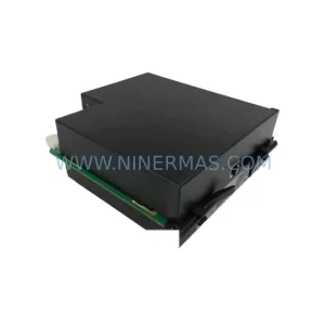
SKU: 269PLUS-100P-120
GE 269PLUS-100P-120 Safety-Reliable Motor Protection Relay
SKU: 469-P5-AI-A1-E-H
GE Multilin 469-P5-AI-A1-E-H Motor Management Relay Retrofit
Catalog Continuation
Alternative parts within SIS Safety & Redundancy Systems.
Stay inside the same system family when you need substitutes, adjacent modules, or a broader shortlist for procurement review.
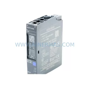
SKU: 6ES7134-6HD00-0BA1
Siemens 6ES7134-6HD00-0BA1 Safety-Reliable Analog Input
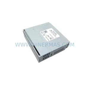
SKU: A5E00110975 G150G130S120
SIEMENS A5E00110975 Safety Drive Module for Critical Sites