Original Industrial Spare Part
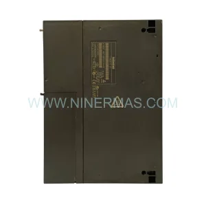
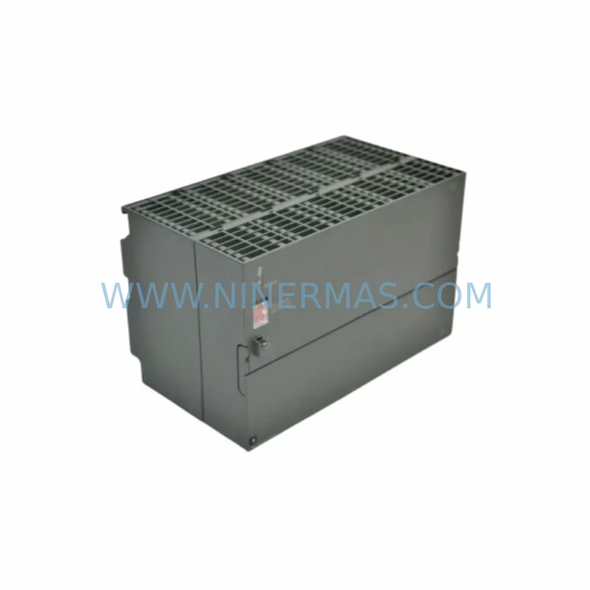
SIEMENS 6ES7307-1KA00-0AA0 Retrofit-Compatible Power Supply
Verify the part, confirm the platform family, and move straight into quotation with the right commercial details.
RFQ Ready
- SKU6ES7307-1KA00-0AA0
- CategoryPLC & Industrial Automation Modules
- BrandSiemens
- SupportAvailability, lead time, condition, and shipping coordination
How Buyers Usually Use This Page
- Confirm the exact part number and platform family before sending the quote request.
- Use direct email when quantity, condition, and destination are already defined internally.
- Switch to the broader brand or category archive when you need alternates nearby.
Series Navigation
Move through the most common platform families behind this part.
Product RFQ
Send this part directly for quotation.
Include quantity, required condition, destination country, and target delivery timing. Current reference: SIEMENS 6ES7307-1KA00-0AA0 Retrofit-Compatible Power Supply with SKU 6ES7307-1KA00-0AA0.
SIEMENS 6ES7307-1KA00-0AA0 Retrofit-Compatible Power Supply for Legacy S7-300 Systems
The SIEMENS 6ES7307-1KA00-0AA0 is a 10 A regulated power supply module designed for the SIMATIC S7-300 series, delivering a stable 24 VDC output to power CPUs, signal modules, and interface modules mounted on the S7-300 rail. As aging S7-300 installations approach end-of-life and original power supply modules become increasingly difficult to source, the 6ES7307-1KA00-0AA0 serves as the authoritative retrofit-compatible replacement — preserving existing rack geometry, terminal wiring, and backplane bus connections without requiring mechanical or electrical redesign of the control cabinet.
For plant engineers managing legacy automation infrastructure, the 6ES7307-1KA00-0AA0 addresses one of the most critical pain points in brownfield modernization: maintaining power continuity to the S7-300 CPU — such as the 6ES7315-2AG10-0AB0 or 6ES7314-1AG14-0AB0 — while avoiding a full platform migration. Because the module slots directly into the standard S7-300 DIN rail profile and uses the same 2-pin L+/M terminal block layout as earlier PS 307 variants, field technicians can complete a hot-swap replacement during a planned maintenance window with minimal downtime.
Upgrade Compatibility Table
| Parameter | 6ES7307-1KA00-0AA0 (This Unit) | Retrofit Notes |
|---|---|---|
| Output Voltage | 24 VDC | Matches all S7-300 CPU and SM module requirements |
| Output Current | 10 A | Replaces 6ES7307-1EA00-0AA0 (5 A) in high-load racks |
| Input Voltage Range | 120/230 VAC, 50/60 Hz | Compatible with global AC supply; no transformer needed |
| Mounting | S7-300 standard DIN rail, left-end slot | Direct drop-in; no rail modification required |
| Terminal Wiring | Screw terminals L1, N, PE (input); L+, M (output) | Identical to predecessor models; existing cable lengths retained |
| Backplane Interface | Passive bus connector (no backplane data bus) | No address configuration required; plug-and-power |
| Compatible CPUs | All S7-300 CPUs (314, 315, 317, 319 series) | Verify total rack current draw does not exceed 10 A |
| Communication Impact | None (power supply only) | PROFIBUS DP, MPI, and PROFINET links unaffected |
| Replacement for | 6ES7307-1EA00-0AA0, 6ES7307-1BA00-0AA0 | Upward-compatible; higher current capacity |
| Warranty | 12-Month Warranty — Tested before shipment, full functional verification | |
Retrofit Planning for Existing Automation Systems
A successful retrofit of the 6ES7307-1KA00-0AA0 begins with a thorough audit of the existing S7-300 rack configuration. Engineers should document the total current consumption of all installed modules — including digital input modules such as the 6ES7321-1BL00-0AA0 (32 DI), digital output modules such as the 6ES7322-1BL00-0AA0 (32 DO), and analog input modules such as the 6ES7331-7KF02-0AB0 — to confirm that the aggregate load remains within the 10 A output rating of the replacement power supply. Exceeding this threshold requires either load redistribution across a second rack via an IM 360/361 interface module pair or selective migration of I/O to a distributed ET 200S or ET 200SP station connected over PROFIBUS DP.
Terminal wiring verification is the next critical step. The 6ES7307-1KA00-0AA0 uses a fixed screw-terminal block for AC input (L1, N, PE) and a separate output terminal (L+, M) that feeds the backplane bus. In most legacy installations, these cables are already sized for 10 A service, but insulation condition and terminal torque should be re-verified per IEC 60204-1 before energizing the replacement module. If the control cabinet also houses a 6ES7307-1BA00-0AA0 (2 A variant) powering a separate 24 VDC field device loop, that circuit remains independent and does not need to be disturbed during the power supply swap.
For installations where the S7-300 CPU communicates with an HMI panel — such as a SIMATIC TP700 Comfort or an older OP 277 — over MPI or PROFIBUS DP, the communication link is maintained through the CPU’s onboard port and is entirely unaffected by the power supply replacement. However, it is good practice to perform a controlled CPU STOP/RUN cycle after the new power supply is installed to allow the CPU to re-initialize all I/O modules and confirm that the HMI tag database reconnects cleanly. If the site uses a SIMATIC S7-300 programming cable (PC Adapter USB) for online diagnostics, this is the ideal moment to run a full hardware configuration comparison in STEP 7 or TIA Portal to verify that the CPU recognizes all modules at their configured slot addresses.
In racks that include a CP 343-1 PROFINET communication processor or a CP 342-5 PROFIBUS DP master, the replacement power supply must be installed and stabilized before these communication modules are powered, as they perform initialization handshakes with the CPU during startup. A power supply with insufficient hold-up time or marginal output voltage can cause intermittent CP faults that are difficult to diagnose without an oscilloscope. The 6ES7307-1KA00-0AA0’s regulated 24 VDC output and built-in short-circuit protection eliminate this risk in properly loaded racks.
Installation space confirmation is straightforward: the module occupies the leftmost slot of the S7-300 rack (Slot 1) and has a fixed width of 80 mm. No additional clearance beyond standard S7-300 cabinet ventilation guidelines is required. If the existing cabinet uses a 6ES7390-1AE80-0AA0 standard rail cut to length, the replacement module mounts without any rail modification.
Downtime Control During System Migration
Minimizing unplanned downtime during a power supply replacement on an active S7-300 system requires a structured pre-outage preparation protocol. Before the maintenance window opens, the site engineer should use STEP 7 or TIA Portal to upload and archive the current CPU program — including all data blocks, organization blocks, and function blocks — to a secure offline backup. This ensures that if the CPU loses its retentive memory during the power cycle (which can occur if the backup battery or supercapacitor is depleted), the program can be reloaded within minutes rather than hours.
The recommended replacement sequence is: (1) place the CPU in STOP mode via the mode selector switch or the programming software; (2) de-energize the rack by switching off the upstream circuit breaker feeding the power supply’s AC input; (3) disconnect the AC input terminals and the 24 VDC output terminals; (4) slide the old power supply off the DIN rail and mount the 6ES7307-1KA00-0AA0 in its place; (5) reconnect terminals in reverse order; (6) re-energize and observe the power supply’s green DC 24V LED and the CPU’s STOP/RUN LED sequence. A healthy startup takes less than 10 seconds from power-on to CPU RUN state in most S7-300 configurations.
Field teams should also verify that any signal isolators or intrinsic safety barriers in the cabinet that draw their auxiliary power from the S7-300 24 VDC bus are within the new power supply’s current budget. These devices are often overlooked during load calculations but can collectively add 0.5–1.5 A to the total rack load. Confirming this before the maintenance window prevents a post-replacement overload trip that would extend the outage.
For sites with strict SLA requirements, a parallel energization strategy can be used: install the 6ES7307-1KA00-0AA0 on a temporary rail segment, pre-wire and test it at bench voltage, then perform the final swap during a sub-5-minute window. This approach is particularly effective when the S7-300 rack controls a process that cannot tolerate extended interruptions, such as a continuous chemical dosing line or a water treatment SCADA node.
Retrofit Support FAQ
Q1: Is the 6ES7307-1KA00-0AA0 a direct replacement for the 6ES7307-1EA00-0AA0?
Yes. The 6ES7307-1KA00-0AA0 (10 A) is fully upward-compatible with the 6ES7307-1EA00-0AA0 (5 A). It uses the same physical form factor, terminal layout, and DIN rail mounting position. No wiring changes are required; the higher current rating provides additional headroom for expanded I/O configurations.
Q2: Will replacing the power supply affect my CPU program or data?
In most cases, no — provided the CPU’s backup battery or integrated supercapacitor is functional and retains memory during the brief power interruption. As a precaution, always upload and save the CPU program to an offline backup before beginning the replacement. If the battery is known to be depleted, plan for a program reload as part of the maintenance procedure.
Q3: What pre-shipment testing is performed on this unit?
Every 6ES7307-1KA00-0AA0 unit supplied by NINERMAS undergoes full functional testing prior to shipment, including output voltage verification at rated load (24 VDC ±1%), short-circuit protection response, and input voltage range confirmation at both 120 VAC and 230 VAC. A test report is available upon request. All units are covered by a 12-month warranty from the date of shipment.
Q4: What is the typical lead time and stock availability?
NINERMAS maintains in-stock inventory of the 6ES7307-1KA00-0AA0 to support urgent retrofit and breakdown replacement requirements. Standard orders ship within 1–3 business days. For large-quantity orders or long-term supply agreements, please contact our sales team to discuss dedicated stock allocation and scheduled delivery programs.
| Product Series | SIMATIC |
|---|---|
| Country of Origin | DE |
Catalog Continuation
More Siemens modules in the catalog.
Use the brand lane to compare nearby part numbers, platform-adjacent modules, and other inquiry-ready listings before sending your final RFQ.
SKU: 99-10-209 424U0471B-05 424U0511C-05 6SL3120-2TE13-0AA3 (UE41PP) Z376A
Siemens 6SL3120-2TE13-0AA3 Safety-Reliable Double Motor Module
SKU: 6ES7138-4FA02-0AB0
Siemens 6ES7138-4FA02-0AB0 Retrofit-Compatible Power Module
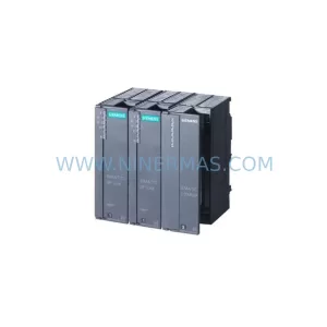
SKU: 6SL3120-2TE13-0AA4 0020-18542 0010-02146 11210-0203RS-001
Siemens 6SL3120-2TE13-0AA4 Service-Ready Spare for Maintenance
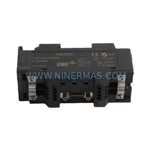
SKU: 6ES7972-4AA02-0XA0
Siemens 6ES7972-4AA02-0XA0 Safety-Reliable PROFIBUS Booster
Catalog Continuation
Alternative parts within PLC & Industrial Automation Modules.
Stay inside the same system family when you need substitutes, adjacent modules, or a broader shortlist for procurement review.
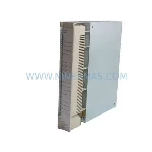
SKU: AI625 3BHT300036R1
ABB AI625 3BHT300036R1 Retrofit Analog Input Module
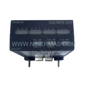
SKU: 3HAC062339-004 3HAC062339-006 lRB7600 3HAC064662-001 DSQC3037 3HAC023195-001
ABB 3HAC062339-004 Service-Ready Spare Part for Industrial Maintenance