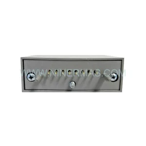
Original Industrial Spare Part
ALSTOM EP3-E-4-EN Retrofit-Compatible Safety Controller
Verify the part, confirm the platform family, and move straight into quotation with the right commercial details.
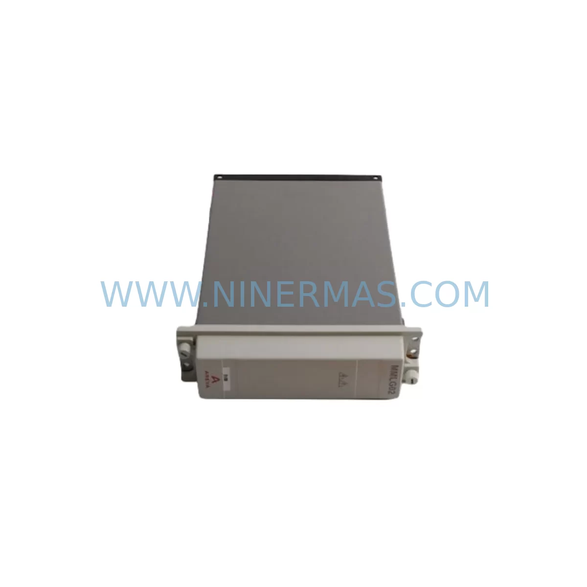
RFQ Ready
- SKUEP3-E-4-EN
- CategorySIS Safety & Redundancy Systems
- BrandALSTOM
- SupportAvailability, lead time, condition, and shipping coordination
How Buyers Usually Use This Page
- Confirm the exact part number and platform family before sending the quote request.
- Use direct email when quantity, condition, and destination are already defined internally.
- Switch to the broader brand or category archive when you need alternates nearby.
Series Navigation
Move through the most common platform families behind this part.
Product RFQ
Send this part directly for quotation.
Include quantity, required condition, destination country, and target delivery timing. Current reference: ALSTOM EP3-E-4-EN Retrofit-Compatible Safety Controller with SKU EP3-E-4-EN.
ALSTOM EP3-E-4-EN Retrofit-Compatible Safety Controller: Legacy System Modernization and Smooth Upgrade Path
The ALSTOM EP3-E-4-EN is a ruggedized safety controller module engineered for demanding industrial environments where control system continuity is non-negotiable. As legacy ALSTOM EP3-series platforms approach end-of-life, plant engineers and automation integrators increasingly rely on the EP3-E-4-EN as a direct retrofit solution — preserving existing rack geometry, terminal wiring, and safety logic while delivering the reliability required for modern compliance standards. Whether you are replacing a failed unit in a running production line or executing a planned control cabinet upgrade, the EP3-E-4-EN provides a validated migration path with minimal disruption to ongoing operations.
Upgrade Compatibility Table
| Parameter | Details |
|---|---|
| SKU / Part Number | EP3-E-4-EN |
| Brand / Manufacturer | ALSTOM |
| Series | EP3 Safety Controller Series |
| Module Type | Ruggedized Safety Controller Module |
| Installation Format | Rack-mount, compatible with EP3-series backplane |
| Communication Compatibility | Compatible with EP3-series communication bus; verify protocol version before installation |
| Replacement Recommendation | Direct replacement for EP3-E-4-EN and functionally equivalent EP3-series safety controller variants |
| Interface / Terminal Wiring | Retain existing terminal block layout; confirm pin assignments against original wiring diagram |
| Commissioning Notes | Verify module address configuration, safety logic download, and HMI screen mapping post-installation |
| Environmental Rating | Ruggedized for harsh environments (vibration, temperature extremes, EMI) |
| Warranty | 12-Month Warranty | Pre-shipment functional testing included |
| Stock Status | Available — contact for lead time confirmation |
Retrofit Planning for Existing Automation Systems
Successful integration of the EP3-E-4-EN into a legacy control system requires a structured pre-installation assessment. Before removing the existing module, engineers should document the current backplane slot assignment, confirm the power supply capacity of the EP3-series rack — typically sourced from an EP3-PS or equivalent ALSTOM power supply module — and verify that available rail current is sufficient to support the replacement controller alongside co-installed I/O modules.
Terminal wiring is a critical checkpoint. The EP3-E-4-EN uses a defined terminal block layout that must be cross-referenced against the original wiring diagram. Any deviation in signal polarity, shielding continuity, or ground reference can introduce faults in the safety loop. Where the original installation used EP3-series digital input modules or EP3-series analog output modules for process feedback, these should be individually tested for signal integrity before the new controller is brought online.
Communication link verification is equally important. The EP3-E-4-EN operates within the EP3 communication architecture, and any upstream SCADA gateway, DCS interface card, or fieldbus coupler — such as a PROFIBUS DP adapter or Modbus RTU bridge — must be confirmed compatible with the module’s firmware revision. In systems where an ALSTOM HMI panel or third-party operator interface is mapped to EP3 controller tags, the HMI screen database should be backed up and validated against the replacement module’s tag structure before cutover.
For installations involving I/O expansion, confirm that any EP3-series remote I/O rack or distributed I/O node connected via the backplane bus is recognized by the replacement controller during the initial power-on sequence. Signal isolators installed between field instruments and the EP3 I/O terminals should be inspected for loop resistance compliance. Programming cables used for safety logic download — typically a dedicated EP3 programming interface cable — must be on-site before the maintenance window begins to avoid unplanned downtime extensions.
Where the legacy system includes an EP3-series communication module for inter-controller data exchange or a redundancy module for hot-standby operation, the replacement EP3-E-4-EN must be configured to match the existing redundancy parameters. Failure to align redundancy settings will prevent the standby controller from synchronizing correctly, creating a single-point-of-failure condition during the transition period.
Downtime Control During System Migration
Minimizing production downtime during an EP3-E-4-EN replacement requires a disciplined pre-outage preparation protocol. The existing safety program — including all function block configurations, safety loop definitions, and interlock logic — must be exported and archived before the module is removed. This backup serves as the reference for post-installation validation and provides a recovery baseline if the commissioning sequence encounters unexpected faults.
Where plant operations permit, a staged cutover approach is recommended: isolate the affected control zone, transfer supervisory control to a parallel system or manual override station, and execute the module swap within a defined maintenance window. The EP3-E-4-EN’s compatibility with the existing backplane eliminates the need for rack modification, reducing physical installation time to the module extraction and re-seating sequence alone.
After installation, the safety logic download should be performed using the archived program file, followed by a structured loop check covering all I/O channels mapped to the replacement controller. HMI communication should be verified by confirming that all operator screen elements reflect live process values. Once loop checks are complete and the safety system has passed its functional test, the control zone can be returned to automatic operation. Pre-shipment testing performed on every EP3-E-4-EN unit shipped by NINERMAS ensures that the module arrives in verified working condition, further reducing the risk of commissioning delays caused by hardware defects.
Retrofit Support FAQ
Q1: Is the EP3-E-4-EN a direct drop-in replacement for the original ALSTOM EP3-series safety controller?
The EP3-E-4-EN is designed as a retrofit-compatible replacement for EP3-series safety controller applications. Physical dimensions and backplane connector geometry are consistent with the EP3 rack standard. Confirm firmware revision and module address settings against your system documentation before installation to ensure full functional equivalence.
Q2: What wiring changes are required when replacing the existing module?
In most retrofit scenarios, existing terminal block wiring can be retained without modification. Cross-reference the original wiring diagram against the EP3-E-4-EN terminal assignment table to confirm signal mapping. Pay particular attention to safety loop wiring, shield grounding, and any field device connections routed through signal isolators.
Q3: How is compatibility with the existing HMI and communication network verified?
Before cutover, back up the HMI tag database and confirm that all controller tags referenced in operator screens are present in the replacement module’s configuration. For fieldbus-connected systems, verify that the EP3-E-4-EN firmware supports the communication protocol version used by the upstream gateway or DCS interface. A communication link test should be performed with the module in bench configuration before installation where possible.
Q4: What warranty and pre-shipment testing does NINERMAS provide for the EP3-E-4-EN?
Every EP3-E-4-EN unit supplied by NINERMAS is covered by a 12-month warranty from the date of shipment. Pre-shipment functional testing is performed on each unit to verify operational integrity before dispatch. In-stock units are available for immediate shipment; contact our team at sale@ninermas.com or +0086 187 5021 5667 to confirm current inventory and lead time.
| Product Series | Other series |
|---|
Catalog Continuation
More ALSTOM modules in the catalog.
Use the brand lane to compare nearby part numbers, platform-adjacent modules, and other inquiry-ready listings before sending your final RFQ.
SKU: NEYRPIC SL1000 V3 669187C/0572
Alstom Neyrpic SL1000 V3 669187C/0572 Retrofit Control Module
SKU: P14DB11A330500A
Alstom P14DB11A330500A Retrofit-Compatible Relay Legacy Systems
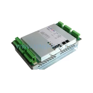
SKU: TTM211 IP166 L54E60000311
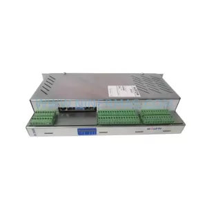
ALSTOM TTM211 IP166 L54E60000311 Safety-Reliable Turbine Control
Catalog Continuation
Alternative parts within SIS Safety & Redundancy Systems.
Stay inside the same system family when you need substitutes, adjacent modules, or a broader shortlist for procurement review.
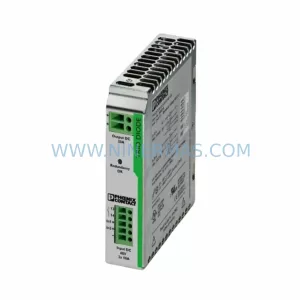
SKU: TRIO-DIODE/48DC/2X10/1X20
Phoenix TRIO-DIODE/48DC/2X10/1X20 Safety-Reliable Redundancy Module
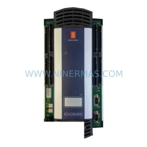
SKU: 810-495659-400 1179A22CR1BV 1350-00682
LAM Research 810-495659-400 Safety-Reliable PSU for Critical Sites