Original Industrial Spare Part
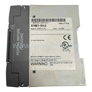
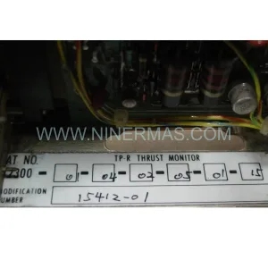
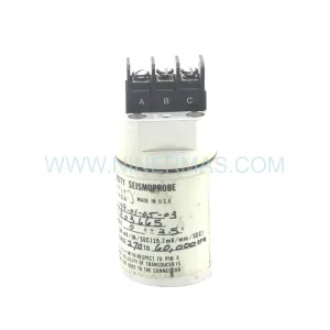
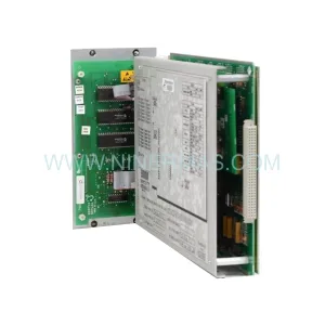
Bently Nevada 21000-28-10-00-041-04-02 Retrofit Module
Verify the part, confirm the platform family, and move straight into quotation with the right commercial details.
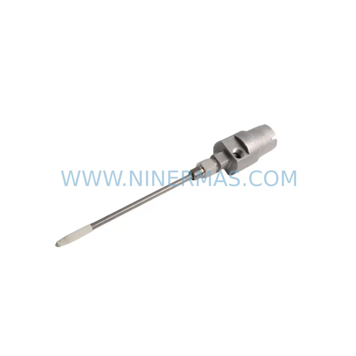
RFQ Ready
- SKU21000-28-10-00-041-04-02
- CategoryTSI & Rotating Machinery Monitoring
- BrandBently Nevada
- SupportAvailability, lead time, condition, and shipping coordination
How Buyers Usually Use This Page
- Confirm the exact part number and platform family before sending the quote request.
- Use direct email when quantity, condition, and destination are already defined internally.
- Switch to the broader brand or category archive when you need alternates nearby.
Series Navigation
Move through the most common platform families behind this part.
Product RFQ
Send this part directly for quotation.
Include quantity, required condition, destination country, and target delivery timing. Current reference: Bently Nevada 21000-28-10-00-041-04-02 Retrofit Module with SKU 21000-28-10-00-041-04-02.
Bently Nevada 21000-28-10-00-041-04-02 Retrofit-Compatible Vibration Monitoring Module for Legacy Systems
The Bently Nevada 21000-28-10-00-041-04-02 is a retrofit-compatible vibration monitoring module designed for seamless integration into existing 21000 Series machinery protection systems. As industrial facilities face increasing pressure to extend the operational life of legacy control architectures while maintaining compliance with modern safety and reliability standards, this module provides a proven, cost-effective path for upgrading aging vibration monitoring infrastructure without requiring a full system replacement.
Whether you are managing a turbine protection panel, a compressor train monitoring rack, or a rotating machinery control cabinet, the 21000-28-10-00-041-04-02 delivers the signal conditioning, proximity probe interface, and output compatibility required to maintain continuous protection during and after the retrofit process. Its form factor and terminal wiring layout are consistent with the broader 21000 Series platform, significantly reducing the engineering effort required for panel modifications and minimizing the risk of wiring errors during installation.
Upgrade Compatibility Table
| Parameter | Legacy Configuration | 21000-28-10-00-041-04-02 |
|---|---|---|
| Module Form Factor | 21000 Series rack-mount | Direct rack-mount, same slot footprint |
| Input Interface | Proximity probe / velocity transducer | Compatible with existing probe wiring |
| Terminal Wiring | Screw-terminal, field-side connector | Identical terminal layout, no rewiring required |
| Output Signal | 4–20 mA / relay contact | 4–20 mA / relay contact, backward compatible |
| Communication | Hardwired I/O to DCS/PLC | Hardwired I/O, compatible with existing DCS loops |
| Power Supply | 24 VDC rack backplane | 24 VDC backplane, same power draw |
| Backplane Interface | 21000 Series backplane connector | Direct backplane plug-in, no adapter required |
| Module Address | DIP switch / jumper configured | Verify address settings match original module |
| Installation Space | Standard 21000 rack slot | Single slot, no additional space required |
| Commissioning | Manual calibration via front panel | Same calibration procedure, existing tools compatible |
| Replacement Recommendation | Direct swap for discontinued 21000 variants | Confirm probe type and gap voltage before swap |
| Warranty | — | 12-Month Warranty included |
Retrofit Planning for Existing Automation Systems
Successful integration of the 21000-28-10-00-041-04-02 into a legacy machinery protection system begins with a thorough pre-retrofit audit. Engineers should document the existing rack configuration, including the positions of all installed modules such as the Bently Nevada 21000 Series keyphasor module, proximitor power supply module, and any 21000 Series relay output modules currently occupying adjacent slots. This documentation ensures that the replacement module is installed in the correct rack position and that backplane signal routing is preserved.
Terminal wiring verification is a critical step. The field-side connector on the 21000-28-10-00-041-04-02 uses the same screw-terminal layout as earlier 21000 Series modules, which means existing probe cables — typically routed from Bently Nevada 3300 XL proximity probes or 7200 Series proximitors — can be reconnected without modification. However, engineers should measure the gap voltage at each probe tip before and after module installation to confirm that the new module’s internal oscillator is driving the probe correctly and that the gap is within the manufacturer’s specified range.
Power capacity planning is equally important. The 21000 Series rack draws power from a dedicated 21000 Series power supply module, and adding or replacing modules can affect the total current draw on the backplane. Before installation, calculate the combined power consumption of all modules in the rack, including any I/O expander modules or communication interface cards that may have been added during previous upgrades. If the existing power supply is operating near its rated capacity, a parallel or upgraded power supply should be sourced before the retrofit begins.
For facilities that have integrated their Bently Nevada system with a DCS or PLC platform — such as a Honeywell Experion, Emerson DeltaV, or Rockwell Automation ControlLogix system — the 4–20 mA output loops from the 21000-28-10-00-041-04-02 must be verified against the existing analog input card configurations. Loop resistance, cable length, and input impedance at the DCS analog input module should all be confirmed to ensure signal integrity is maintained after the module swap. If the facility uses a Modbus RTU or HART communication overlay for condition monitoring data, the communication link should be tested with the new module in place before the system is returned to service.
HMI screen updates may also be required. If the existing operator interface terminal or SCADA system displays vibration trend data sourced from the 21000 Series rack, the engineering team should verify that the tag names, scaling factors, and alarm setpoints associated with the replaced module are correctly mapped to the new module’s output. In many cases, the HMI configuration can be preserved without modification, but this should be confirmed during the factory acceptance test or bench test phase before the module is shipped to site.
Downtime Control During System Migration
Minimizing unplanned downtime during a 21000 Series module replacement requires careful coordination between the maintenance team, the control room operator, and the reliability engineer. The recommended approach is to perform a hot-standby verification before taking the existing module offline: confirm that all vibration channels monitored by the module are reading within normal operating ranges, that no active alarms are present, and that the machinery being protected can be safely isolated or bypassed for the duration of the swap.
Where the process cannot be interrupted, a temporary bypass relay or a portable vibration monitor can be used to maintain protection coverage on the affected channels while the permanent module is being replaced. This approach is particularly important for critical rotating equipment such as steam turbines, gas compressors, or boiler feed pumps, where a loss of vibration monitoring coverage — even for a short period — may trigger a safety interlock or violate a regulatory requirement.
The physical module swap itself typically takes less than 15 minutes for an experienced technician. The 21000-28-10-00-041-04-02 is designed for tool-free extraction from the rack backplane, and the field-side terminal connector can be disconnected and reconnected without disturbing the probe cable routing. After installation, the module should be powered up and allowed to stabilize for a minimum of 15 minutes before calibration checks are performed. The original program logic in the connected PLC or DCS does not require modification, as the module’s output signal format and scaling are identical to the unit being replaced.
Post-installation verification should include a channel-by-channel comparison of vibration amplitude readings between the new module and any adjacent reference channels, a relay output function test to confirm that trip and alert setpoints are active, and a review of the event log in the connected condition monitoring system to confirm that no spurious alarms were generated during the swap. All test results should be documented and retained as part of the facility’s maintenance record for the affected machinery train.
Retrofit Support FAQ
Q1: Is the 21000-28-10-00-041-04-02 a direct replacement for all discontinued 21000 Series vibration modules?
A: The 21000-28-10-00-041-04-02 is designed as a retrofit-compatible replacement within the 21000 Series platform. Before ordering, confirm the specific sub-model of the module being replaced by checking the label on the front panel of the existing unit. Key parameters to verify include the input transducer type (proximity probe or velocity), the output signal range, and the relay configuration. Our technical team can assist with cross-reference verification prior to shipment.
Q2: What pre-shipment testing is performed on each unit?
A: Every 21000-28-10-00-041-04-02 module undergoes a full functional test prior to shipment, including input signal simulation, output loop calibration verification, relay contact operation test, and backplane connector integrity check. A test report is available upon request. Each unit is shipped with a 12-month warranty covering manufacturing defects and functional failures under normal operating conditions.
Q3: Can the module be installed without modifying the existing probe wiring or terminal blocks?
A: In the majority of retrofit applications, the existing field wiring can be reconnected directly to the 21000-28-10-00-041-04-02 without modification. The terminal layout is consistent with the standard 21000 Series field connector. However, if the existing installation uses non-standard cable terminations or if the terminal block has been modified during a previous repair, a wiring inspection should be performed before installation to confirm compatibility.
Q4: What is the typical lead time and inventory availability?
A: We maintain stock inventory of the 21000-28-10-00-041-04-02 to support urgent replacement requirements. Standard lead time for in-stock units is 3–5 business days for international shipments. For projects requiring multiple units or scheduled maintenance outages, we recommend confirming availability and placing a reservation order in advance to ensure supply continuity. All units are covered by a 12-month warranty from the date of shipment.
| Product Series | 21000 Series |
|---|---|
| Country of Origin | US |
Catalog Continuation
More Bently Nevada modules in the catalog.
Use the brand lane to compare nearby part numbers, platform-adjacent modules, and other inquiry-ready listings before sending your final RFQ.
SKU: 330703-000-026-10-01-05
Bently Nevada 330703-000-026-10-01-05 Retrofit Proximity Probe
SKU: 330104-01-14-10-01-00
Bently Nevada 330104-01-14-10-01-00 Retrofit-Compatible Proximitor for Legacy Systems
SKU: 330104-10-18-10-02-00
Bently Nevada 330104-10-18-10-02-00 Safety-Reliable Proximity Transducer Module
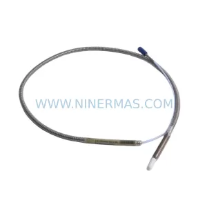
SKU: 330910-00-02-10-02-00
Bently Nevada 330910-00-02-10-02-00 Safety Relay for Critical Control
Catalog Continuation
Alternative parts within TSI & Rotating Machinery Monitoring.
Stay inside the same system family when you need substitutes, adjacent modules, or a broader shortlist for procurement review.
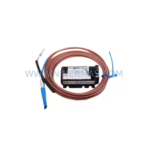
SKU: PR6423/004-030 CON021/913-030
Emerson PR6423/004-030 CON021/913-030 Retrofit Proximity System
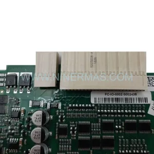
SKU: FC-IO-0002 CC V1.1
Honeywell FC-IO-0002 CC V1.1 | Original I/O Module Spare Parts
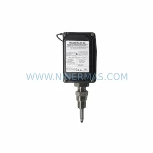
SKU: 330880-28-15-035-00-02
Bently Nevada 330880-28-15-035-00-02 Proximity Transducer
SKU: 330101-00-09-20-02-05
Bently Nevada 330101-00-09-20-02-05 Retrofit-Compatible Proximitor for Legacy Systems