Original Industrial Spare Part
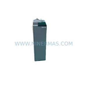
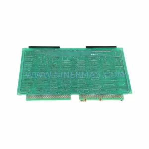
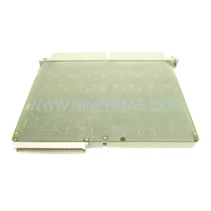
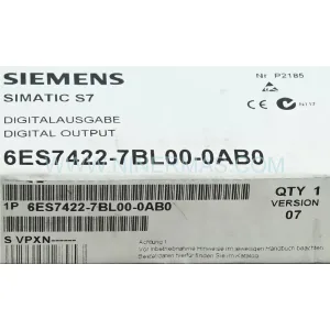
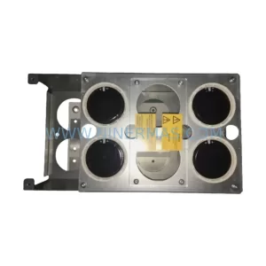
Siemens 6ES5451-7LA12 Retrofit Digital Output Module
Verify the part, confirm the platform family, and move straight into quotation with the right commercial details.
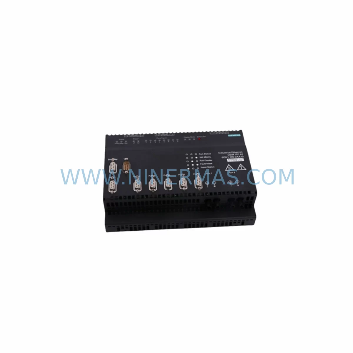
RFQ Ready
- SKU6ES5451-7LA12
- CategoryPLC & Industrial Automation Modules
- BrandSiemens
- SupportAvailability, lead time, condition, and shipping coordination
How Buyers Usually Use This Page
- Confirm the exact part number and platform family before sending the quote request.
- Use direct email when quantity, condition, and destination are already defined internally.
- Switch to the broader brand or category archive when you need alternates nearby.
Series Navigation
Move through the most common platform families behind this part.
Product RFQ
Send this part directly for quotation.
Include quantity, required condition, destination country, and target delivery timing. Current reference: Siemens 6ES5451-7LA12 Retrofit Digital Output Module with SKU 6ES5451-7LA12.
Siemens 6ES5451-7LA12 Retrofit Digital Output Module: Legacy S5 System Compatibility & Smooth Upgrade
The Siemens 6ES5451-7LA12 is a ruggedized 32-channel digital output module designed for the SIMATIC S5 programmable logic controller platform. As a retrofit-compatible replacement for discontinued S5-series output modules, the 6ES5451-7LA12 enables engineers and maintenance teams to extend the operational life of existing control cabinets, legacy production lines, and distributed I/O architectures without requiring a full PLC migration. With a 24 VDC output signal, robust backplane interface, and compatibility with the S5-115U, S5-135U, and S5-155U controller families, this module remains one of the most sought-after spare parts for industrial automation modernization projects worldwide.
NINERMAS maintains verified in-stock inventory of the 6ES5451-7LA12, backed by a 12-month warranty and pre-shipment functional testing. Each unit is inspected against original Siemens factory specifications before dispatch, ensuring reliable drop-in performance in your existing rack and backplane environment.
Upgrade Compatibility Table
| Parameter | 6ES5451-7LA12 Specification | Retrofit / Replacement Notes |
|---|---|---|
| Output Channels | 32 × Digital Output (DO) | Verify load current per channel ≤ 0.5 A; check aggregate current against backplane bus rating |
| Output Voltage | 24 VDC | Confirm field device supply voltage matches; no step-down adapter required for standard 24 VDC actuators |
| Backplane Interface | S5 parallel bus (U-bus) | Compatible with S5-115U / S5-135U / S5-155U racks; verify slot assignment in STEP 5 hardware configuration |
| Module Address | Configurable via DIP switch | Match address to original module before insertion; document existing address before removal |
| Installation Form Factor | Standard S5 single-width slot | No mechanical adapter required; confirm rack slot clearance and cable duct space |
| Communication Protocol | S5 parallel backplane (non-Profibus) | If migrating to S7 / Profibus DP, an ET 200M IM 153-x interface module is required as a bridge |
| Programming Environment | SIMATIC STEP 5 v7.x | Retain original AWL/FUP program blocks; no re-programming required for like-for-like swap |
| Wiring Terminal | 40-pin front connector (6ES5490-8xx00) | Reuse existing front connector if undamaged; inspect terminal screws and cable ferrules before reconnection |
| Operating Temperature | 0 °C to +60 °C | Ruggedized variant; suitable for harsh industrial environments with vibration and dust exposure |
| Warranty | 12-Month Warranty — all units pre-tested before shipment by NINERMAS | |
Retrofit Planning for Existing Automation Systems
Replacing the 6ES5451-7LA12 within a live or recently decommissioned S5 control system requires careful pre-planning across several engineering disciplines. The following workflow reflects best practices gathered from field retrofit projects across automotive, chemical processing, water treatment, and discrete manufacturing environments.
Power Budget Verification: Before installing the replacement module, audit the total current draw on the S5 rack’s internal power supply — typically a Siemens 6ES5955-3LC41 or 6ES5955-3LF41 power supply unit. The 6ES5451-7LA12 draws load current from both the backplane logic bus and the external 24 VDC field supply. Confirm that the aggregate output load across all installed DO modules does not exceed the PSU’s rated output capacity. If the existing power supply is marginal, consider upgrading to a higher-capacity unit or adding a supplementary Siemens 6ES5980-0xx0 expansion power supply before commissioning the new module.
Front Connector and Terminal Wiring: The 6ES5451-7LA12 uses a 40-pin front connector, typically the 6ES5490-8JA00 or 6ES5490-8JB00 variant. Before removing the faulty module, photograph or document all terminal assignments. Label each wire with its I/O address and signal description. If the existing front connector shows signs of corrosion, cracked housing, or loose terminal screws, replace it with a new connector to avoid intermittent faults after the module swap. Reusing a damaged connector on a new module is a common cause of post-retrofit field failures.
Backplane Slot and Module Address Configuration: The S5 backplane assigns I/O addresses based on physical slot position and DIP switch settings on the module itself. Before inserting the 6ES5451-7LA12, verify the DIP switch address configuration matches the original module’s documented address. Mismatched addresses will cause the STEP 5 program to reference incorrect output bytes, resulting in unexpected actuator behavior during the first power-on test. Cross-reference the hardware configuration in your STEP 5 project file — particularly the Systemdaten block — to confirm slot-to-address mapping.
Program Logic and HMI Screen Compatibility: A like-for-like replacement of the 6ES5451-7LA12 requires no changes to the STEP 5 AWL (Statement List) or FUP (Function Block Diagram) program. However, if the retrofit is part of a broader migration from S5 to SIMATIC S7-300 or S7-400, the output module’s I/O addresses must be remapped in the new hardware configuration. In such cases, HMI screens built on Siemens WinCC or ProTool/Pro will require tag address updates to reflect the new S7 memory areas. Plan for a dedicated HMI validation session after program migration to confirm all output status displays and alarm triggers function correctly.
Communication Link Integrity: In systems where the S5 controller communicates upstream via Siemens CP 5431 FMS/DP or CP 5511 communication processors, verify that the communication link remains stable during the module swap. Momentary backplane interruptions during hot-swap attempts on non-hot-swap-rated S5 racks can cause the CP module to lose its Profibus DP token, requiring a manual restart of the communication processor. Schedule the swap during a planned maintenance window and coordinate with the SCADA or DCS operator to suppress alarms during the replacement window.
I/O Expansion and Signal Isolation: In applications where the 6ES5451-7LA12 drives inductive loads such as solenoid valves, motor contactors, or relay coils, confirm that adequate signal isolation is in place. Inductive kickback from unprotected loads can damage output transistors over time. If the original installation lacked suppression diodes or RC snubber circuits at the load terminals, add them during the retrofit to extend the new module’s service life. For applications requiring galvanic isolation between the PLC output and the field device, consider adding a Siemens SITOP signal isolator or equivalent DIN-rail-mounted isolator module within the control cabinet.
Installation Space and Cable Management: Confirm that the target rack slot has adequate physical clearance for the 6ES5451-7LA12’s front connector and cable bundle. In densely populated S5 racks — particularly those using 6ES5700-series sub-racks or 6ES5183-3UA11 expansion units — cable duct space adjacent to the slot may be constrained. Route new wiring through existing cable ducts where possible, and avoid sharp bends near the front connector to prevent conductor fatigue over time.
Downtime Control During System Migration
Minimizing unplanned downtime is the primary operational concern during any S5 digital output module replacement. The following strategies have been validated across multiple field retrofit projects and are recommended for all 6ES5451-7LA12 swap operations.
Pre-Staging and Bench Testing: Configure the replacement 6ES5451-7LA12’s DIP switches and verify its address settings on the bench before bringing it to the installation site. If a spare S5 rack or test fixture is available, perform a functional output test using a 24 VDC bench supply and indicator lamps connected to the front connector terminals. This eliminates the risk of discovering a configuration error after the production rack has been opened.
Program Backup Before Any Hardware Change: Upload and archive the complete STEP 5 project — including all program blocks (OB, PB, FB, DB), system data, and hardware configuration — to a secure engineering workstation before touching any hardware. Use the SIMATIC STEP 5 v7.23 or later software to perform a full online upload. Store the backup on both local storage and a network share. This ensures that the original program logic can be restored within minutes if an unexpected fault occurs during the swap.
Controlled Power-Down Sequence: Follow the documented power-down sequence for the S5 rack: place the CPU (e.g., 6ES5948-3UA21 or 6ES5928-3UB21) in STOP mode via the mode selector switch, then de-energize the rack’s power supply. Do not remove the module while the rack is powered — the S5 parallel bus is not designed for hot-swap operation, and live removal can damage the backplane connectors and adjacent modules.
Commissioning and First Power-On: After installing the 6ES5451-7LA12 and reconnecting the front connector, restore power to the rack and place the CPU in RUN mode. Monitor the module’s LED indicators: the green RUN LED should illuminate, and no red FAULT LED should be active. Use a STEP 5 online monitoring session via a Siemens PG 740 or a PC with a CP 5611 or CP 5512 MPI/Profibus adapter to force individual output bits and verify field device response. Document the commissioning test results and retain them as part of the maintenance record for the installation.
Fallback Plan: Retain the removed 6ES5451-7LA12 (even if faulty) until the replacement has been confirmed operational in production for at least one full shift. In some cases, a module that appears failed may have a recoverable fault (e.g., a blown output fuse or a tripped thermal protection circuit) that can be addressed by a qualified repair facility, providing a secondary spare at reduced cost.
Retrofit Support FAQ
Q1: Is the 6ES5451-7LA12 a direct drop-in replacement for other S5 digital output modules such as the 6ES5451-7LA11 or 6ES5452-8MR11?
The 6ES5451-7LA12 is functionally compatible with the 6ES5451-7LA11 in most S5-115U and S5-135U applications, sharing the same 32-channel DO architecture and front connector pinout. The 6ES5452-8MR11 is a relay output variant with a different electrical interface and is not a direct substitute. Always verify the output type (transistor vs. relay), channel count, and voltage rating before substituting modules across different part numbers.
Q2: What commissioning steps are required after installing the replacement module?
After physical installation, verify DIP switch address settings match the original module, reconnect the front connector, restore rack power, and place the CPU in RUN mode. Use STEP 5 online monitoring to force each output channel and confirm field device response. Check all LED indicators on the module face. Document the test results and update the maintenance log. No program changes are required for a like-for-like swap.
Q3: Can NINERMAS supply the 6ES5451-7LA12 with a tested and verified warranty?
Yes. All 6ES5451-7LA12 units supplied by NINERMAS are pre-tested against original Siemens factory specifications before shipment. Each unit is covered by a 12-month warranty from the date of delivery. In the event of a warranty claim, NINERMAS will arrange replacement or repair at no additional cost to the customer. Contact sale@ninermas.com for warranty registration and claim procedures.
Q4: What is the typical lead time and stock availability for the 6ES5451-7LA12?
NINERMAS maintains ready stock of the 6ES5451-7LA12 for immediate dispatch. Standard orders are processed within 1–2 business days, with international shipping available to the US, EU, UK, Japan, and other industrial markets. For large-quantity procurement or long-term spare-parts programs, contact our sales team to discuss dedicated stock reservation and scheduled delivery arrangements.
| Product Series | SIMATIC S5 |
|---|---|
| Country of Origin | DE |
Catalog Continuation
More Siemens modules in the catalog.
Use the brand lane to compare nearby part numbers, platform-adjacent modules, and other inquiry-ready listings before sending your final RFQ.
SKU: 6ES7193-6BP20-0BB0
Siemens 6ES7193-6BP20-0BB0 Retrofit BaseUnit for Legacy Systems
SKU: 6SL3055-0AA00-5MA0 A5E33412837
SIEMENS 6SL3055-0AA00-5MA0 Safety-Reliable Inverter Control Module
Catalog Continuation
Alternative parts within PLC & Industrial Automation Modules.
Stay inside the same system family when you need substitutes, adjacent modules, or a broader shortlist for procurement review.