Original Industrial Spare Part
CYBOR 25823-18 Retrofit-Compatible Pump for Legacy Systems
Verify the part, confirm the platform family, and move straight into quotation with the right commercial details.
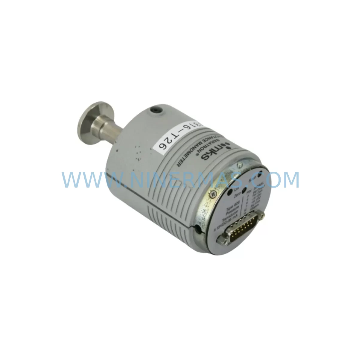
RFQ Ready
- SKU25823-18 & 25823-T4-18 5026-00 B1
- CategorySIS Safety & Redundancy Systems
- BrandCYBOR
- SupportAvailability, lead time, condition, and shipping coordination
How Buyers Usually Use This Page
- Confirm the exact part number and platform family before sending the quote request.
- Use direct email when quantity, condition, and destination are already defined internally.
- Switch to the broader brand or category archive when you need alternates nearby.
Series Navigation
Move through the most common platform families behind this part.
Product RFQ
Send this part directly for quotation.
Include quantity, required condition, destination country, and target delivery timing. Current reference: CYBOR 25823-18 Retrofit-Compatible Pump for Legacy Systems with SKU 25823-18 & 25823-T4-18 5026-00 B1.
CYBOR 25823-18 Retrofit-Compatible Pump for Legacy Systems
The CYBOR 25823-18 is a precision photoresist pump controller engineered for seamless integration into legacy semiconductor dispensing systems. As fabs and process lines face increasing pressure to extend equipment lifecycles while maintaining yield and throughput, the 25823-18 provides a validated retrofit path that preserves original process parameters without requiring full tool replacement. Whether you are replacing an end-of-life unit, upgrading a photoresist track, or restoring a dispensing system after an unplanned failure, the 25823-18 delivers the mechanical and electrical compatibility required for a controlled, low-risk transition.
The CYBOR 25823-T4-18 and 5026-00-B1 are closely related variants within the same pump family. The 25823-T4-18 shares the same fluidic architecture and port geometry as the 25823-18, making it a direct candidate for cross-reference evaluation during retrofit planning. The 5026-00-B1 serves as the primary dispense valve assembly paired with this pump body, and its condition should be assessed alongside the pump controller during any scheduled maintenance or emergency replacement. Confirming that both the pump and valve assembly are sourced from the same production revision minimizes the risk of flow calibration drift after reinstallation.
Before initiating a retrofit, engineers should verify the supply voltage and current draw against the existing power distribution panel. The 25823-18 operates within a defined DC voltage range, and any deviation from the original wiring harness specification must be corrected before commissioning. Terminal block assignments on the legacy controller chassis should be mapped against the replacement unit’s I/O pinout to avoid signal inversion or ground loop issues. If the existing system uses a CYBOR 25823-20 or a comparable earlier-generation pump body, the mounting footprint and fluid port orientation are compatible, but the electrical connector housing may differ and require an adapter harness.
Upgrade Compatibility Table
| Parameter | CYBOR 25823-18 | Legacy Reference (25823-T4-18 / 5026-00-B1) |
|---|---|---|
| Mounting Interface | Standard CYBOR flange, 4-bolt pattern | Compatible — same bolt pattern and port spacing |
| Fluid Port Size | 1/4″ PVDF compression fitting | Compatible — confirm fitting torque spec |
| Electrical Connector | Molex 8-pin locking header | Verify pin-out against legacy harness; adapter may be required |
| Control Signal | Analog 0–10 V / digital pulse input | Compatible with most legacy track controllers |
| Communication Protocol | RS-232 / RS-485 selectable | Confirm baud rate and termination resistor setting |
| Installation Space | Standard CYBOR pump bay envelope | No modification required for same-generation chassis |
| Replacement Recommendation | Direct drop-in for 25823-18 and 25823-T4-18 | Evaluate 5026-00-B1 valve assembly simultaneously |
| Commissioning Focus | Flow calibration, dispense volume verification, leak check | Run 50-cycle dispense test before returning to production |
| Warranty | 12 months from shipment date | Covers pump body, valve assembly, and controller PCB |
Retrofit Planning for Existing Automation Systems
A successful photoresist pump retrofit requires a structured approach that accounts for every interface between the pump and the surrounding process environment. The 25823-18 sits at the center of a dispensing subsystem that typically includes a Pall Ultipleat filter housing upstream, an SMC ITV-series pneumatic regulator controlling back-pressure, and a Parker solenoid valve managing the dispense enable signal. Each of these components must be inspected and pressure-tested before the new pump is brought online. A failed filter housing or a leaking solenoid valve will corrupt the dispense volume calibration and may damage the replacement pump within the first production run.
On the control side, the track controller — often a legacy system running a proprietary recipe format — communicates with the pump via RS-232 or RS-485. Before disconnecting the original unit, capture the full communication log and confirm the baud rate, parity, and stop-bit configuration. If the fab is migrating from an older CYBOR 25823-20 platform to the 25823-18, the recipe parameters for dispense volume, purge cycle duration, and suck-back distance will need to be re-entered and validated against the new pump’s flow curve. Do not assume that the original recipe values will produce identical dispense volumes on the replacement unit without running a calibration sequence.
For systems that include a Brooks Automation wafer handler or a comparable robotic arm interfacing with the coat module, the dispense timing window must be re-synchronized after the pump replacement. Any change in pump response latency — even within the manufacturer’s specification — can shift the dispense start point relative to the wafer rotation angle, resulting in edge coverage defects. Coordinate with the track software engineer to adjust the dispense trigger offset before releasing the tool to production wafers.
If the retrofit involves a control cabinet upgrade, confirm that the VAT gate valve controller and any associated interlock relays are compatible with the new pump’s digital I/O voltage levels. The 25823-18 uses 24 VDC logic levels on its digital inputs, and older cabinet wiring designed for 12 VDC or 5 VDC logic will require level-shifting relays or a wiring harness modification. Signal isolation modules — such as those from the Phoenix Contact MINI MCR series — are recommended at the interface between the pump controller and any legacy PLC I/O card to prevent ground loop interference from corrupting the dispense command signal.
Where the existing system includes an Entegris IntelliGen Mini chemical delivery module upstream of the pump, verify that the delivery pressure setpoint is within the 25823-18’s inlet pressure specification. Overpressure at the pump inlet is a common cause of premature diaphragm wear and will void the warranty. Install a calibrated pressure gauge at the pump inlet port during commissioning and document the steady-state and transient pressure readings before closing the process enclosure.
Downtime Control During System Migration
Minimizing unplanned downtime during a photoresist pump replacement requires pre-staging all replacement components before the tool is taken offline. The 25823-18, the 5026-00-B1 valve assembly, and any associated filter elements and O-ring kits should be on the bench and inspected before the maintenance window begins. A pre-shipment functional test is performed on every unit prior to dispatch, and the test report should be reviewed to confirm that the pump’s flow rate and dispense volume are within specification before installation begins.
The original program logic stored in the track controller must be backed up before any wiring is disturbed. If the track uses a proprietary recipe format, export the full recipe library and store it on a separate medium. Do not rely on the controller’s internal memory as the sole backup. Once the replacement pump is installed and the wiring is verified, restore the recipe library and run a dry-cycle test — with the chemical supply isolated — to confirm that all motion sequences and timing parameters execute correctly before introducing photoresist to the system.
Field commissioning should follow a staged approach: first verify electrical continuity and signal integrity, then perform a water-based flow calibration, and finally run a photoresist dispense qualification with test wafers before releasing the tool to production. This sequence protects the original process parameters, maintains field control continuity, and reduces the risk of a second unplanned outage caused by a commissioning error. Target total downtime for a planned 25823-18 replacement — including pre-staging, installation, and qualification — is four to six hours for an experienced maintenance team.
Retrofit Support FAQ
Q1: Is the CYBOR 25823-18 a direct replacement for the 25823-T4-18?
Yes. The 25823-18 and 25823-T4-18 share the same fluidic port geometry and mounting footprint. The primary difference is in the controller PCB revision. Confirm the electrical connector pinout against your existing harness before installation. In most cases, the replacement is a direct drop-in with no mechanical modification required.
Q2: What commissioning steps are required after installation?
After mechanical installation and wiring verification, perform a 50-cycle dispense test using the process chemical at the production setpoint. Measure dispense volume at cycles 1, 10, 25, and 50 to confirm stability. Adjust the dispense time parameter in the track recipe if the measured volume deviates by more than ±2% from the target. Document all calibration data before returning the tool to production.
Q3: Does the 12-month warranty cover the 5026-00-B1 valve assembly?
Yes. The 12-month warranty covers the pump body, the 5026-00-B1 valve assembly, and the controller PCB when supplied as a matched set. Warranty claims require the original shipment documentation and a completed failure report. Units that show evidence of overpressure, chemical incompatibility, or unauthorized disassembly are excluded from warranty coverage.
Q4: What is the lead time, and is reserved stock available?
Stock units are available for immediate shipment. For customers with ongoing maintenance programs or multi-tool fleets, reserved inventory arrangements are available to guarantee supply against scheduled maintenance windows. Contact our sales team to discuss a long-term supply commitment that aligns with your planned maintenance calendar.
| Product Series | Legacy |
|---|
Catalog Continuation
Alternative parts within SIS Safety & Redundancy Systems.
Stay inside the same system family when you need substitutes, adjacent modules, or a broader shortlist for procurement review.
SKU: 6SE7090-0XX84-3EH0
Siemens 6SE7090-0XX84-3EH0 Safety-Reliable Drive for Critical Control
SKU: SST-PB3-CLX-RLL
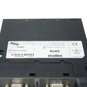
Allen-Bradley SST-PB3-CLX-RLL | Industrial PROFIBUS DP Scanner