Original Industrial Spare Part
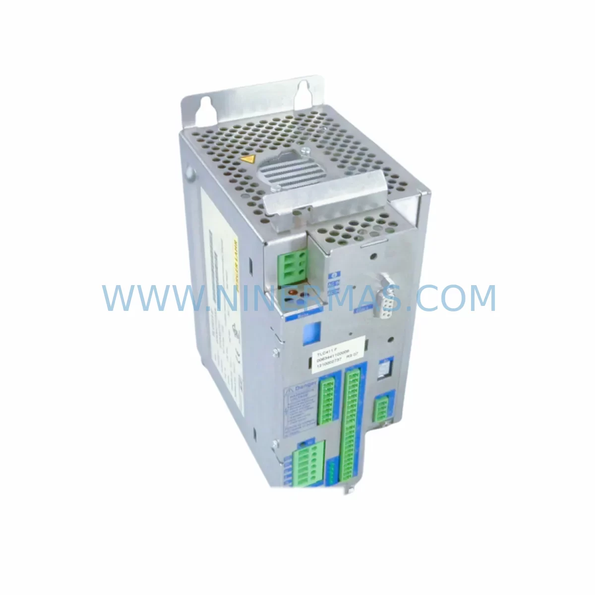
BERGER LAHR TLC411F Service-Ready Spare Part for Industrial Maintenance
Verify the part, confirm the platform family, and move straight into quotation with the right commercial details.
RFQ Ready
- SKUTLC411F
- CategoryPLC & Industrial Automation Modules
- BrandBerger Lahr
- SupportAvailability, lead time, condition, and shipping coordination
How Buyers Usually Use This Page
- Confirm the exact part number and platform family before sending the quote request.
- Use direct email when quantity, condition, and destination are already defined internally.
- Switch to the broader brand or category archive when you need alternates nearby.
Series Navigation
Move through the most common platform families behind this part.
Product RFQ
Send this part directly for quotation.
Include quantity, required condition, destination country, and target delivery timing. Current reference: BERGER LAHR TLC411F Service-Ready Spare Part for Industrial Maintenance with SKU TLC411F.
BERGER LAHR TLC411F Service-Ready Spare Part for Industrial Maintenance
The BERGER LAHR TLC411F is a compact stepper motor control module engineered for demanding industrial environments. Designed to operate within BERGER LAHR’s established stepper drive ecosystem, the TLC411F delivers reliable pulse-direction control, integrated protection circuitry, and a robust form factor suited to continuous-duty automation cabinets. For maintenance engineers managing aging production lines, the TLC411F represents a critical spare that can restore motion control functionality with minimal downtime and without requiring extensive system reconfiguration.
In facilities where BERGER LAHR stepper systems have been in service for a decade or more, sourcing a verified replacement TLC411F is often the fastest path to resuming production. Unlike generic substitutes, a tested and warranted TLC411F maintains the original signal interface, step resolution settings, and thermal envelope expected by the host controller — eliminating the risk of parameter mismatch or unexpected axis behavior after replacement.
Spare Maintenance Table
| Parameter | Details |
|---|---|
| SKU / Part Number | TLC411F |
| Brand / Manufacturer | BERGER LAHR |
| Series | TLC / Stepper Control Series |
| Module Type | Stepper Motor Controller |
| Control Interface | Pulse / Direction (Step & Dir) |
| Typical Supply Voltage | 24 VDC (logic); motor supply per drive spec |
| Mounting | DIN rail / panel mount (confirm with enclosure drawing) |
| Operating Temperature | 0 °C to +55 °C (standard industrial range) |
| Protection Class | IP20 (cabinet installation) |
| Compatibility | BERGER LAHR stepper drive systems; legacy TLC-series racks |
| Replacement Suitability | Direct replacement for TLC411F in existing installations |
| Pre-Shipment Testing | Function-tested before dispatch |
| Warranty | 12 Months from date of shipment |
| Origin | Germany |
Maintenance Planning for Continuous Operation
Effective spare parts planning for a BERGER LAHR TLC411F installation extends well beyond the controller module itself. Maintenance engineers conducting annual cabinet inspections or responding to unplanned stoppages should treat the TLC411F replacement as an opportunity to audit the surrounding electrical infrastructure.
Begin with the 24 VDC logic power supply feeding the TLC411F. A degraded or undersized power supply — such as an aging SITOP PSU100S or equivalent DIN-rail unit — can cause intermittent faults that mimic controller failure. Verify output voltage under load and check for ripple before reinstalling the new module. Similarly, inspect the motor power supply or drive amplifier stage; in many BERGER LAHR configurations, the TLC411F interfaces with a companion power stage module, and both units should be evaluated together.
Terminal blocks and wiring harnesses connected to the TLC411F deserve close attention. Phoenix Contact or Weidmüller screw-clamp terminal strips in older cabinets may show signs of oxidation or loose torque, particularly on the step/direction signal lines and enable inputs. Re-torque all terminals and replace any discolored or brittle wiring before commissioning the replacement module.
If the TLC411F is part of a multi-axis system, inspect the neighboring axis modules — such as additional TLC-series controllers or BERGER LAHR WDP stepper drives — for signs of thermal stress or parameter drift. A single failed axis often indicates that adjacent modules have been operating under elevated thermal load. Checking the backplane connector integrity and rack power distribution at this stage prevents repeat failures.
For systems that include a PLC or motion controller issuing step/direction commands — whether a Siemens S7-300 with FM357 positioning module, a Schneider Electric Modicon M340, or a standalone indexer — verify that the pulse output frequency and signal levels remain within the TLC411F’s input specifications. Signal isolators or line drivers may be required if cable runs exceed recommended lengths or if electrical noise is present in the cabinet.
Relay output modules used for enable/disable sequencing, fault reset, and e-stop integration should also be inspected. Worn relay contacts on units such as OMRON G2R or Phoenix Contact PLC-RSC relay modules can introduce timing errors that prevent the TLC411F from initializing correctly after power-up. Replace any relay showing contact resistance above specification.
Finally, review the HMI or operator panel connected to the motion system. If the facility uses a Siemens TP700 Comfort or similar panel for axis jogging and fault acknowledgment, confirm that the screen graphics and alarm messages correctly reflect the TLC411F’s fault output states. Outdated HMI project versions may not display new fault codes introduced by firmware differences between TLC411F production batches.
Site Replacement Workflow
A structured on-site replacement of the BERGER LAHR TLC411F minimizes downtime and reduces the risk of commissioning errors. Follow this sequence to ensure a safe and efficient swap:
Step 1 — Documentation: Before powering down, photograph the existing wiring, record all DIP switch or parameter settings visible on the installed TLC411F, and note the axis address or station number assigned in the host controller configuration.
Step 2 — Safe Isolation: Isolate the cabinet using the main disconnect and verify absence of voltage on both the logic supply and motor power rails. Follow local LOTO (Lockout/Tagout) procedures. Allow capacitors in the motor power stage to discharge fully before handling connectors.
Step 3 — Module Removal: Disconnect the step/direction signal connector, the enable input wiring, and the motor power connector in sequence. Release the DIN rail locking tab and slide the TLC411F clear of the rack. Inspect the vacated slot for debris, corrosion, or damaged connector pins.
Step 4 — New Module Preparation: Set the replacement TLC411F’s DIP switches and any jumper configurations to match the documented settings from Step 1. Do not power the module before installation.
Step 5 — Installation and Wiring: Seat the new TLC411F on the DIN rail, reconnect all signal and power connectors, and verify terminal torque. Restore logic power first and confirm the module’s status LED sequence before applying motor power.
Step 6 — Functional Verification: Command a low-speed jog move from the HMI or PLC and confirm correct direction, step count, and fault-free operation. Log the replacement date, module serial number, and test results in the site maintenance record.
This workflow typically allows a trained technician to complete a TLC411F replacement within one to two hours, keeping unplanned downtime to a minimum and ensuring the system returns to full specification.
Spare Parts Support FAQ
Q1: Is the replacement TLC411F tested before shipment?
Yes. Every TLC411F unit dispatched by NINERMAS undergoes functional testing prior to packaging. Test records are available on request. The module is shipped with protective packaging to prevent ESD damage and mechanical stress during transit.
Q2: What is the warranty coverage for the TLC411F?
NINERMAS provides a 12-month warranty from the date of shipment. This covers manufacturing defects and functional failures under normal operating conditions. Warranty claims are supported by our technical team at sale@ninermas.com.
Q3: Can you supply the TLC411F on a long-term or scheduled basis?
Yes. NINERMAS maintains stock of BERGER LAHR TLC411F modules and can support scheduled procurement programs for facilities managing multi-year maintenance plans. Contact us to discuss volume pricing, lead time commitments, and consignment stock arrangements.
Q4: How do I confirm compatibility before ordering?
Provide your existing module’s part number, any suffix codes visible on the nameplate, and the host system or rack model. Our technical team will verify compatibility and advise on any wiring or parameter differences between production batches before shipment.
| Product Series | Other series |
|---|---|
| Country of Origin | US |
Catalog Continuation
More Berger Lahr modules in the catalog.
Use the brand lane to compare nearby part numbers, platform-adjacent modules, and other inquiry-ready listings before sending your final RFQ.
SKU: WDP5-118.051-00
Berger Lahr WDP5-118.051-00 Safety-Reliable Stepper Drive
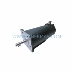
SKU: RDM51122/50 LWC RDM51122/50LWC
BERGER LAHR RDM51122/50 LWC Retrofit-Compatible Stepping Motor for Legacy Systems
Catalog Continuation
Alternative parts within PLC & Industrial Automation Modules.
Stay inside the same system family when you need substitutes, adjacent modules, or a broader shortlist for procurement review.
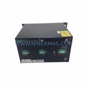
SKU: SCE906A2-002-01 SCE906A200201
Pacific Scientific SCE906A2-002-01 Retrofit Servo Amplifier
SKU: EPC500 3183062451
Alfa Laval EPC500 3183062451 Service-Ready Spare Part