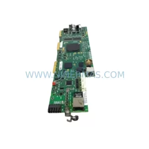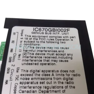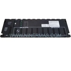
Original Industrial Spare Part
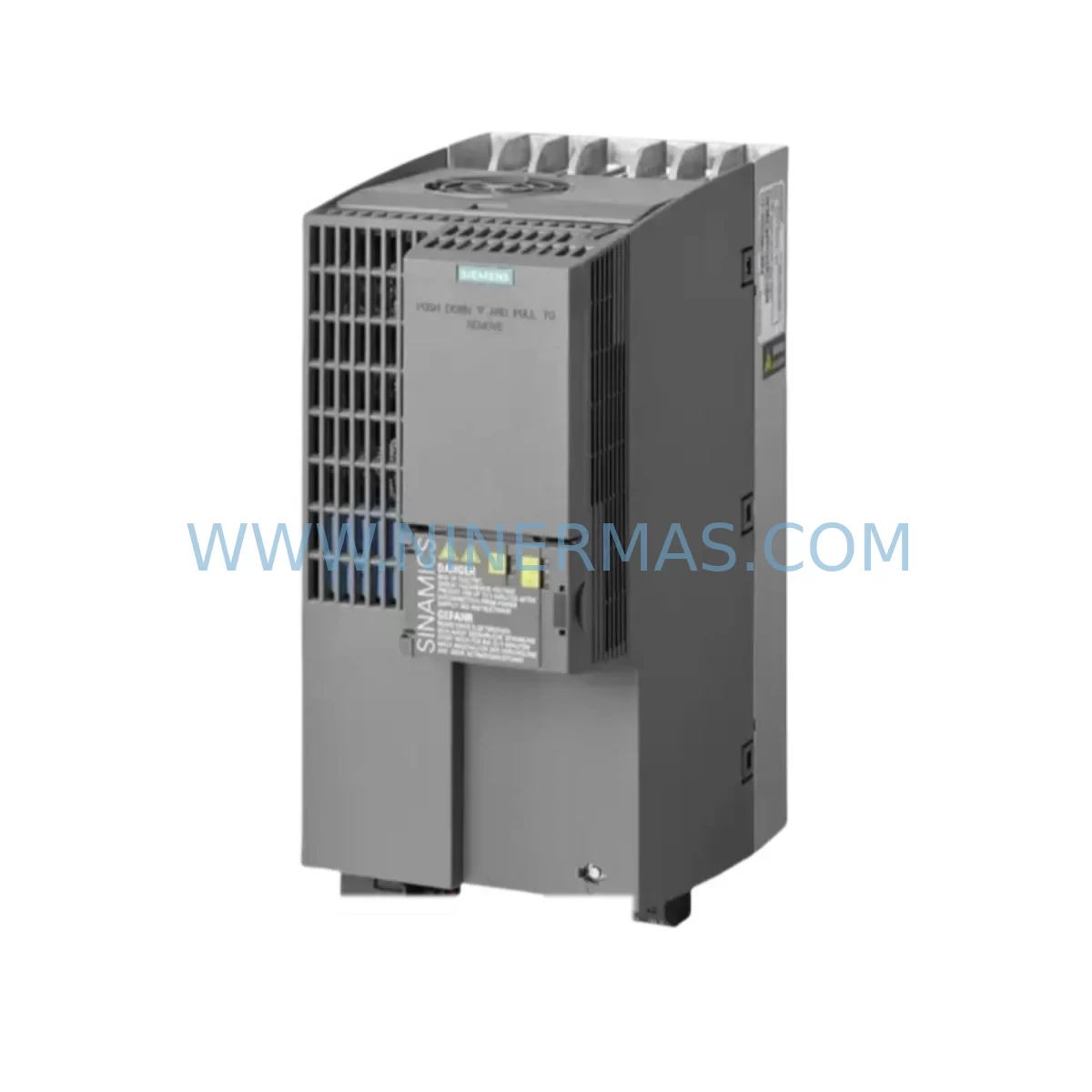
SIEMENS 6SL3352-1AE37-5BA1 Retrofit-Compatible Frequency Converter
Verify the part, confirm the platform family, and move straight into quotation with the right commercial details.
RFQ Ready
- SKU6SL3352-1AE37-5BA1
- CategoryPLC & Industrial Automation Modules
- BrandSiemens
- SupportAvailability, lead time, condition, and shipping coordination
How Buyers Usually Use This Page
- Confirm the exact part number and platform family before sending the quote request.
- Use direct email when quantity, condition, and destination are already defined internally.
- Switch to the broader brand or category archive when you need alternates nearby.
Series Navigation
Move through the most common platform families behind this part.
Product RFQ
Send this part directly for quotation.
Include quantity, required condition, destination country, and target delivery timing. Current reference: SIEMENS 6SL3352-1AE37-5BA1 Retrofit-Compatible Frequency Converter with SKU 6SL3352-1AE37-5BA1.
SIEMENS 6SL3352-1AE37-5BA1 Retrofit-Compatible Frequency Converter for Legacy System Modernization
The SIEMENS 6SL3352-1AE37-5BA1 is a ruggedized frequency converter module designed for demanding industrial environments and is widely deployed as a retrofit-compatible replacement within legacy SINAMICS S120 drive system architectures. As automation engineers face increasing pressure to extend the operational life of aging control infrastructure, this module provides a reliable, drop-in upgrade path that preserves existing wiring topologies, program logic, and cabinet layouts while delivering the performance and diagnostics expected of modern drive technology.
Whether you are managing a planned retrofit of an older SINAMICS S120 booksize or chassis installation, responding to an unplanned failure of a discontinued drive module, or executing a phased modernization of a multi-axis production line, the 6SL3352-1AE37-5BA1 addresses the core challenges of legacy system replacement: power capacity alignment, terminal compatibility, backplane interface continuity, module addressing, program migration, HMI screen mapping, communication link integrity, physical installation clearance, and on-site commissioning workflow.
Upgrade Compatibility Table
| Parameter | Details |
|---|---|
| SKU / Part Number | 6SL3352-1AE37-5BA1 |
| Series | Siemens SINAMICS S120 |
| Module Type | Ruggedized Frequency Converter Module |
| Typical Replacement Target | Legacy SINAMICS S120 Motor Modules, discontinued booksize drive units |
| Backplane / Rack Interface | DRIVE-CLiQ compatible; verify Drive-CLiQ hub module (e.g. DMC20 / DME20) firmware version before installation |
| Communication Protocol Compatibility | PROFIBUS DP, PROFINET IO; confirm CU320-2 or CU310-2 Control Unit firmware alignment |
| Power Supply Requirement | Verify Smart Line Module or Active Line Module (e.g. 6SL3130 series) DC bus capacity before substitution |
| Terminal / Wiring Adaptation | Check motor cable cross-section, PE bonding, and shield termination against original installation drawings |
| Installation Space | Confirm booksize slot width and cooling airflow clearance in existing control cabinet |
| Commissioning Tool | STARTER or SINAMICS Startdrive (TIA Portal); parameter set upload/download via SIMATIC Memory Card recommended |
| Warranty | 12 Months from date of shipment |
Retrofit Planning for Existing Automation Systems
Successful integration of the 6SL3352-1AE37-5BA1 into an existing automation system begins well before the module arrives on site. Engineers should start by auditing the current DC bus loading across all Motor Modules sharing the same Active Line Module or Smart Line Module (6SL3130 series). Adding or replacing a drive unit changes the aggregate power demand, and the line module must have sufficient headroom to support the new configuration without triggering overcurrent or DC bus overvoltage faults during acceleration ramps.
Terminal wiring is the next critical checkpoint. The original motor cable routing, shield grounding strategy, and PE conductor sizing must be verified against the 6SL3352-1AE37-5BA1 connection diagram. In many legacy installations, motor cables were sized for an earlier generation of drive hardware with different output current ratings. If the replacement module operates at a higher continuous output current, cable derating calculations should be revisited before energizing the system.
The backplane interface deserves particular attention in multi-axis S120 configurations. The Drive-CLiQ topology — including any DMC20 or DME20 hub modules used to extend the Drive-CLiQ network to remote I/O or encoder feedback devices — must be mapped and verified. Each node on the Drive-CLiQ ring carries a unique component identifier, and inserting a replacement module may require updating the drive object topology in the CU320-2 or CU310-2 Control Unit project. Failure to update the topology can result in F07220 or A07221 alarms that prevent the axis from enabling.
Module addressing and drive object assignment within the SIMATIC S7 or TIA Portal project must also be reviewed. If the legacy system used a PROFIBUS DP connection between the Control Unit and the S7-300 or S7-400 PLC, the GSD file and hardware configuration in STEP 7 must reflect the replacement module’s telegram type and process data word mapping. For systems already migrated to PROFINET IO with a S7-1500 or ET 200SP controller, the GSDML file and device name assignment in TIA Portal should be confirmed before the first test run.
Program compatibility is a frequent concern during S120 retrofits. The existing BICO (Binector-Connector) interconnections, setpoint channel configuration, and safety function parameterization stored in the CU320-2 must be exported and re-imported after the hardware replacement. Using a SIMATIC Memory Card to back up the complete parameter set before removing the old module is strongly recommended. This also preserves the motor data identification results and speed controller tuning, avoiding the need for a full re-commissioning cycle.
HMI screen mapping should be validated if the installation includes a SIMATIC HMI panel — such as a KTP700 or TP1500 Comfort Panel — with drive status displays or parameter write functions linked to specific drive object numbers. A change in drive object addressing can silently break HMI read/write connections without generating a visible alarm, leading to operator confusion during the first production run after the retrofit.
Communication link integrity between the drive system and any upstream SCADA or DCS layer should be tested under simulated load conditions before returning the line to production. This includes verifying that cyclic process data exchange, acyclic parameter access via DP/V1 or PROFINET record data, and fault message routing all function correctly with the replacement module in place.
Physical installation clearance is often underestimated in dense control cabinet layouts. The 6SL3352-1AE37-5BA1 booksize form factor requires adequate vertical and horizontal clearance for cooling airflow, and the cabinet door must close fully with all cables dressed and secured. If the original installation used a different booksize width, adapter brackets or cabinet modifications may be required.
Downtime Control During System Migration
Minimizing unplanned downtime during a drive module replacement requires a structured pre-outage preparation protocol. Before the scheduled maintenance window, the engineering team should complete a full parameter backup from the existing CU320-2 or CU310-2 Control Unit, document all BICO interconnections, photograph the existing wiring and cable routing, and prepare a commissioning checklist that covers power-up sequence, fault acknowledgment, direction of rotation verification, and speed reference scaling confirmation.
During the outage window, the replacement sequence should follow a defined order: isolate and lock out the incoming supply to the Active Line Module, discharge the DC bus capacitors (verify with a calibrated voltmeter before touching any DC bus conductors), remove the legacy Motor Module, install the 6SL3352-1AE37-5BA1, reconnect motor cables and Drive-CLiQ connections, restore power, and perform a controlled first-run test at reduced speed setpoint before releasing the axis to full production speed.
Protecting the original program logic is non-negotiable. The parameter backup stored on the SIMATIC Memory Card should be treated as the authoritative restore point. If the commissioning tool detects a firmware version mismatch between the replacement module and the Control Unit, a firmware update should be performed before loading the parameter set, not after, to avoid parameter incompatibility errors that can corrupt the drive configuration.
Maintaining field control continuity during the migration is particularly important in process industries where a sudden loss of drive control can trigger cascade shutdowns or product quality excursions. Where possible, the retrofit should be staged during a planned production break, and a dry-run simulation using the SINAMICS Startdrive offline project should be completed before the live outage to identify any parameter conflicts or topology mismatches in advance.
Retrofit Support FAQ
Q1: Is the 6SL3352-1AE37-5BA1 a direct replacement for my existing SINAMICS S120 Motor Module?
A: The 6SL3352-1AE37-5BA1 is designed as a retrofit-compatible replacement within the SINAMICS S120 booksize family. Before installation, confirm that the power rating, DC bus voltage class, and Drive-CLiQ interface version are compatible with your existing Control Unit and Line Module. Our technical team can assist with compatibility verification prior to shipment.
Q2: What commissioning steps are required after installing the replacement module?
A: After physical installation and wiring, restore the parameter set from your SIMATIC Memory Card backup using STARTER or SINAMICS Startdrive. Verify the Drive-CLiQ topology, confirm drive object addressing in your PLC project, perform a motor data identification run if the motor has changed, and execute a controlled test run at reduced speed before returning to full production. All units are pre-tested before shipment to reduce on-site commissioning time.
Q3: How do I verify terminal wiring compatibility before installation?
A: Compare the 6SL3352-1AE37-5BA1 connection diagram against your existing motor cable cross-sections, shield termination points, and PE bonding arrangement. Pay particular attention to the U2/V2/W2 motor output terminals and the DC bus P/N connections. If your original installation used a different output current rating, recalculate cable derating before energizing. Contact our support team for wiring adaptation guidance specific to your cabinet layout.
Q4: What does the 12-month warranty cover, and what is your stock availability?
A: All units supplied by NINERMAS carry a 12-month warranty from the date of shipment, covering manufacturing defects and functional failures under normal operating conditions. We maintain in-stock inventory of the 6SL3352-1AE37-5BA1 and can confirm lead time and quantity availability upon inquiry. Expedited shipping options are available for urgent breakdown situations.
| Product Series | SINAMICS |
|---|---|
| Country of Origin | DE |
Catalog Continuation
More Siemens modules in the catalog.
Use the brand lane to compare nearby part numbers, platform-adjacent modules, and other inquiry-ready listings before sending your final RFQ.
SKU: 99-10-209 424U0471B-05 424U0511C-05 6SL3120-2TE13-0AA3 (UE41PP) Z376A
Siemens 6SL3120-2TE13-0AA3 Safety-Reliable Double Motor Module
SKU: 6ES7138-4FA02-0AB0
Siemens 6ES7138-4FA02-0AB0 Retrofit-Compatible Power Module
SKU: 6SL3120-2TE13-0AA4 0020-18542 0010-02146 11210-0203RS-001
Siemens 6SL3120-2TE13-0AA4 Service-Ready Spare for Maintenance
SKU: 6ES7972-4AA02-0XA0
Siemens 6ES7972-4AA02-0XA0 Safety-Reliable PROFIBUS Booster
Catalog Continuation
Alternative parts within PLC & Industrial Automation Modules.
Stay inside the same system family when you need substitutes, adjacent modules, or a broader shortlist for procurement review.
SKU: AI625 3BHT300036R1
ABB AI625 3BHT300036R1 Retrofit Analog Input Module
SKU: 3HAC062339-004 3HAC062339-006 lRB7600 3HAC064662-001 DSQC3037 3HAC023195-001
ABB 3HAC062339-004 Service-Ready Spare Part for Industrial Maintenance